HS50_advance_level 1_20200522_221201 (1).pdf - 第401页
Editi on 06/2002 S tudent Guide HS - 50 Advance d I 1 1 Pneumat ic Cutter and Emp ty-T ap e Duct 14 11.5 Dia grams of Pneumatic System an d Function al Sequence F ig. 11 .5 .1 Dia gram o f P ne umat ic Sy stem : Cutt er …

Student Guide HS-50 Advanced I Edition 06/2002
11 Pneumatic Cutter and Empty-Tape Duct
13
Key to Fig. 11.4.3 (left):
1. Empty-tape duct assembly
2. Cover plate
3. Screws fastening the cover plate
4. Direction to remove the cover plate, fastening: 4 socket hex head cap screws M4 x 8
5. Stationary blade, fastened with: 2 socket hex head cap screws M6 x 35
6. Protective sheet (remains mounted)
7. Deflector plate (deflects small chips of tape)
8. 2 socket hex head cap screws M4 x 8
9. Screws fastening the articulated joint to the movable blade (see also Fig. 11.6.4):
10. Rubber-metal vibration damper (4 x ), each fastened with
1 socket hex head cap screw M 4 x 20 (top),
1 socket hex head cap screw M 4 x 35 (bottom)
and any disk and spring washer (4 DIN 127-A) installed underneath them
11. Tape waste chute (baffle in the machine frame)
12.Screws fastening the cutter, 2 socket hex head cap screws M 6 x 25
13. Baffle, inside
14. Screws M4 x 20, self-tapping
15. Baffle, outside
16. Screws M4 x 20, self-tapping
17. Reject box (profile)
18. Screws M4 x 16, self-tapping
19. Tape deflector
Edition 06/2002 Student Guide HS-50 Advanced I
11 Pneumatic Cutter and Empty-Tape Duct
14
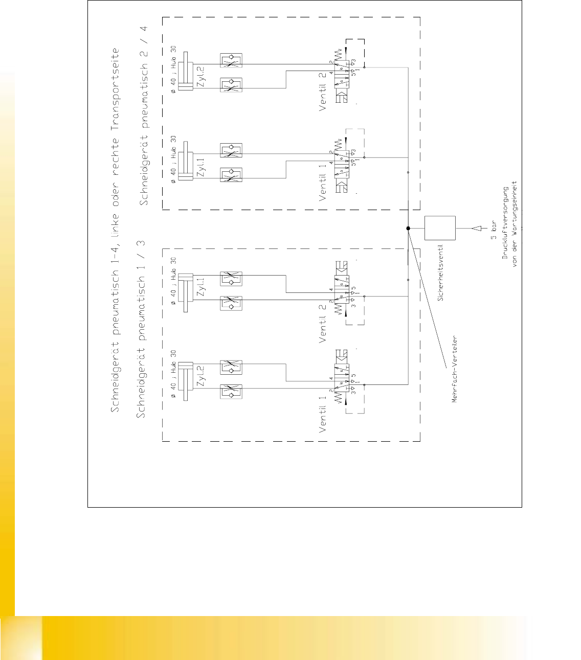
11.5 Diagrams of Pneumatic System and Functional
Sequence
Fig. 11.5.1 Diagram of Pneumatic System: Cutter per Conveyor Side
Student Guide HS-50 Advanced I Edition 06/2002
11 Pneumatic Cutter and Empty-Tape Duct
15
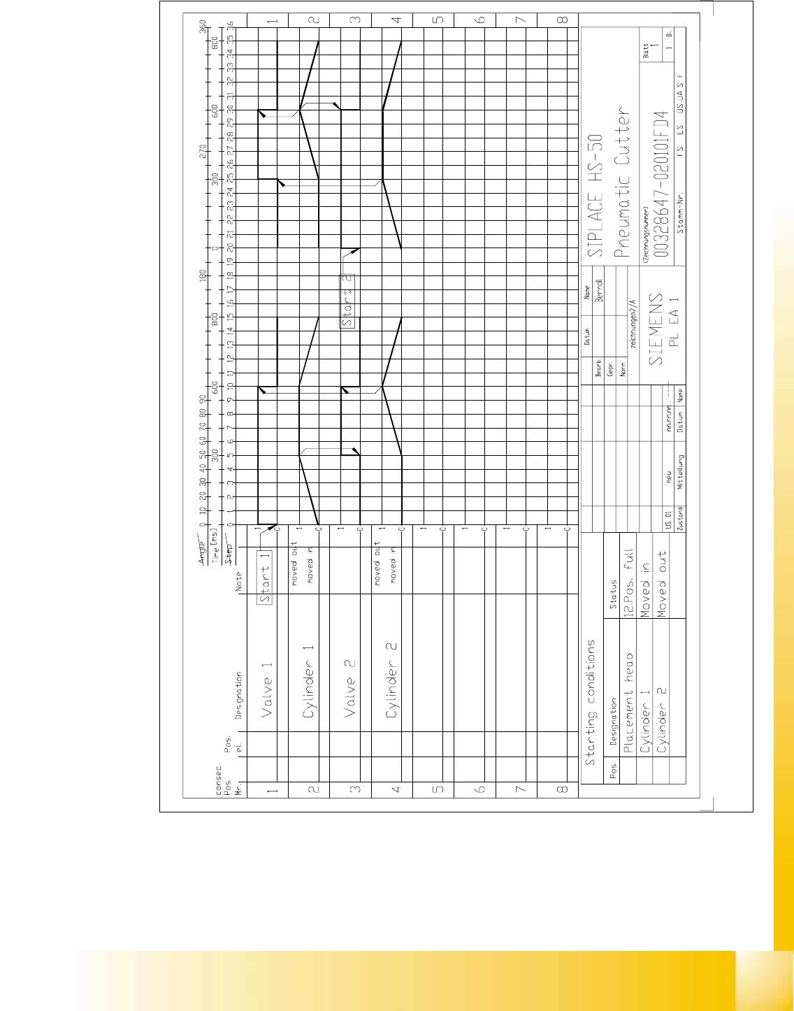
Fig. 11.5.2 Diagram of Functional Sequence