HS50_advance_level 1_20200522_221201 (1).pdf - 第403页
Editi on 06/2002 S tudent Guide HS - 50 Advance d I 1 1 Pneumat ic Cutter and Emp ty-T ap e Duct 16 11.6 Resolving Prob lems DAN G E R Strictly adhere to the instructions in t h e DANGER text in Section 11.1 ! 11 W ARNIN…
Student Guide HS-50 Advanced I Edition 06/2002
11 Pneumatic Cutter and Empty-Tape Duct
15
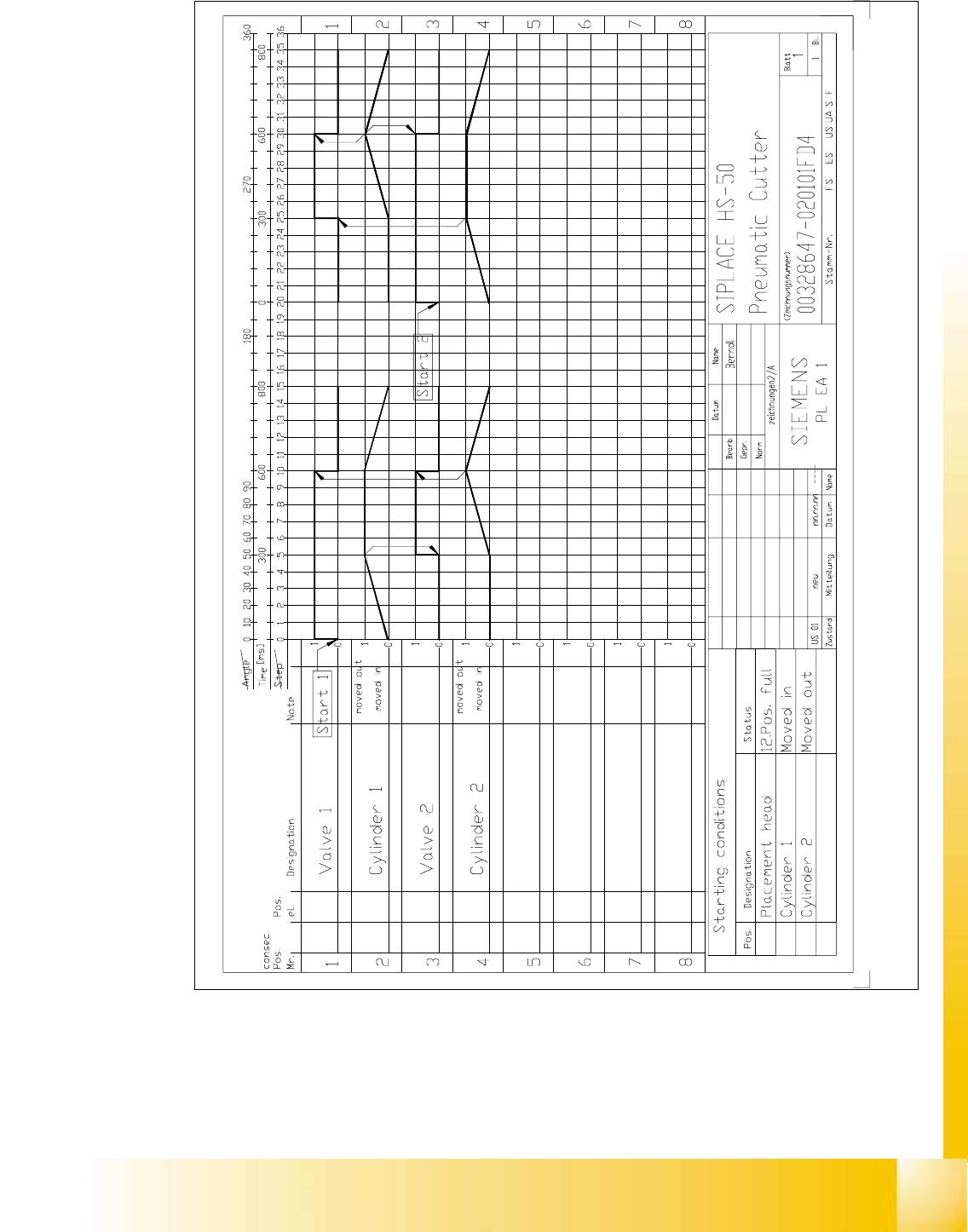
Fig. 11.5.2 Diagram of Functional Sequence
Edition 06/2002 Student Guide HS-50 Advanced I
11 Pneumatic Cutter and Empty-Tape Duct
16
11.6 Resolving Problems
DANGER
Strictly adhere to the instructions in the DANGER text in Section 11.1 ! 11
WARNING
Wear appropriate thick protective gloves whenever working near the blades / the tape deflector.
High risk of injury exists from stationary blade and movable blade and the tape deflector of the
cutter, even when the machine has been turned off.
Never reach into the pneumatic cutter from below or into the empty-tape duct from above, not even
to resolve a problem (e.g., when tape is jammed). 11
11.6.1 Exchanging the Pneumatic Cutter
WARNING
Wear appropriate thick protective gloves.
When removing the cutter, hold it only on the left and right, on the outside.
Never support the cutter on your body, e.g., on your knees or thighs.
Do not place your feet under the cutter.
You could injury yourself severely or at least damage your clothing.
Make certain that no one can injury themselves on the cutter after it has been dismantled. 11
11.6.1.1 Removing the Cutter
à Turn the machine and then the compessed air ON.
à Disconnect the movable component changeover table from the machine and move it out of the
machine.
à Turn the machine OFF, disconnect the machine from the mains and turn off the flow of com-
pressed air at the compressed air unit. Actuate the needle valve on the compressed air unit to
bleed the compressed air lines (see DANGER text in Section 11.1).
Student Guide HS-50 Advanced I Edition 06/2002
11 Pneumatic Cutter and Empty-Tape Duct
17
à Loosen the screws fastening the nozzle changer, lift it up somewhat and hold it in this position.
à Unplug the electrical cable and the pneumatic hose of the nozzle changer.
à Carefully put the nozzle changer down.
à Loosen the screws fastening the empty-tape duct assembly (see Fig. 11.4.1 -> 11, 9) and lift
the duct out of the machine.
WARNING
There is always a risk of injuring yourself with the cutting edge of the blades.
For this reason, the deflector plate, the cover and the protective sheet (see Fig. 11.4.3 -> 6,7, 2)
must be left mounted in place. 11
à Take the cover off the cable pit (see Fig. 11.6.6 -> 5).
à Loosen the cutter’s compressed air connection (Y-socket union: see Fig. 11.6.3 -> 9) in the
cable pit (see Fig. 11.6.6 -> 5).
à Remove the cover from the control board (see Fig. 11.6.5 -> 14).
à Unplug the plug-and-socket connection of the power supply and the drive on the control board
(see Fig. 11.6.5 -> 11, 10).
à Carefully undo the corresponding cable tie (left or right) on the outside of the control board box
(see Fig. 11.6.5 -> 15).
-> Do not damage the cables in this process.
à Place the cover back on the control board and on the cable pit.
à Remove the tape chute (it is only hooked in).
This makes the cutter easier to access for removal.
WARNING
The area under the cutter must be clear (e.g., do not place your feet under it either). 11
à Undo the fasteners for the stop buffer assembly on left- and right-hand side of the machine
frame (two M8 socket hex head cap screws on each side, see Fig. 11.4.1 -> 15) under the
surface supporting for the component table.
à Loosen the screws fastening the cutter to the machine frame (2 screws, M6, on the left and
right retaining bracket, see Fig. 11.4.1 -> 2, 3 and 4):
– In exceptional cases, disks or plates may have been installed between the contact surface
of the cutter on the machine frame and the cutter itself.
-> Save these disks / plates and re-install them later.
à Securely hold the cutter tight at both ends.