HS50_advance_level 1_20200522_221201 (1).pdf - 第408页
S tud ent Guid e HS-50 A dvanced I E dition 06/2 002 1 1 P neumatic Cutt er and Empty- T ape Du ct 21 à Di smantle the deflector plate: four M4 x 8 socket he x head c ap screws , see F ig. 11.4.2 -> 13 ). à Lo osen th…
Edition 06/2002 Student Guide HS-50 Advanced I
11 Pneumatic Cutter and Empty-Tape Duct
20
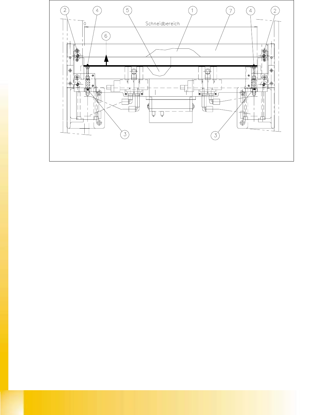
Fig. 11.6.1 Removing/Installing Stationary and Movable Blade
Key:
1. Stationary blade
2. Fastening of the stationary blade (under the deflector plate):
2 Socket hex head cap screws M6 x 35
3. Articulated joint
4. Screws fastening the articulated joint in the movable blade:
1 Socket hex head cap screws M4 x 25 each, Strength 12.9, Loctite no. 243
5. Movable blade under the tape deflector
6. Direction for removing the movable blade
7. Deflector plate, see also Fig. 11.4.2

Student Guide HS-50 Advanced I Edition 06/2002
11 Pneumatic Cutter and Empty-Tape Duct
21
à Dismantle the deflector plate: four M4 x 8 socket hex head cap screws, see Fig. 11.4.2 -> 13).
à Loosen the screws fastening the stationary blade at left and right (2 screws M4, see Fig. 11.6.1
-> 2).
à Mark the mounting position of the stationary blade (on the blade) with a water-insoluble marker
(-> right end = right).
à Take hold of the stationary blade by its ends and lift it out of the machine.
à Holding the articulated joint with a size 10 open-end wrench (see Fig. 11.6.1 -> 3), loosen the
screws fastening the articulated joint in the movable blade (1 screw each at right and left, see
Fig. 11.6.1 -> 4).
à Push the movable blade in parallel until it is in the mounting position of the stationary blade
(move it towards the PCB conveyor, see Fig. 11.6.1 -> 6):
Using a tool such as a screwdriver, move the blade by alternately prying on the left and right
next to the compressed air cylinder.
à Mark the mounting position of the movable blade (on the blade) with a water-insoluble marker
(right end = right).
à Lift the movable blade out of the cutter in this position.
11.6.2.2 Installing the Blades
WARNING
Wear thick protective gloves.
You might cut yourself on the blades and the tape deflector.
Never reach into the pneumatic cutter from below or into the empty-tape duct from above. 11
CAUTION
Tighten the screws to the correct torque -> see Table, Fig. 11.4.2.
All parts must be clean before installing. 11
à Wear thick protective gloves !
Make certain that the blades are clean. If they are not, wipe all of their surfaces very carefully
with a clean cloth which has been folded several times.
-> Do not use any grease dissolving agents (see CAUTION text in Section 11.6.3.2).
à Turn the movable blade 180 ° on its vertical axis to the previous marked mounting position:
-> The right-hand end of the blade must now be on the left.
à Insert the movable blade into the cutter in this angle of rotation and push it in parallel back into
the original mounting position.

Edition 06/2002 Student Guide HS-50 Advanced I
11 Pneumatic Cutter and Empty-Tape Duct
22
à Apply Loctite no. 243 (Item no.: see Section 11.3) to the two M4 screws fastening the articu-
lated joint in the movable blade (details: see Fig. 11.6.2 -> 4).
à Re-insert these screws in the left and right of the movable blade.
NOTE:
Make certain that the midline / open-end wrench surface of the articulated joint is at right angles
to the slide surface of the movable blade (see Fig. 11.6.4 -> 5 and 6) and so that the articulated
joint can slide smoothly in the slot (= prevents turning) in the movable blade. 11
à Using the size 10 open-end wrench to hold the appropriate articulated joint, tighten both
screws.
à Afterwards, rotate the stationary blade 180° on its vertical axis to the original mounting posi-
tion,insert it into the cutter in this position and screw it tight.
– The right-hand end of the blade must now be on the left.
à Install the stationary blade (see Fig. 11.6.1 -> 1, 2).
à Assemble the cutter in the reverse order to disassembly (see Section 11.6.2.1).
à Remove the parallel clamps from the cutter or dismantle the cutter from the mounting plate.
à Mount the cutter in the machine, as described in Section 11.6.1.2.
à Install the empty-tape duct assembly and check the entire length of the gap between the lead-
ing edge of the tape deflector and the "empty-tape baffle, inside", as described in Section
11.6.8.
à Perform the appropriate “Final Steps” (see Section 11.6.11).