HS50_advance_level 1_20200522_221201 (1).pdf - 第41页
Studen t Guide HS-50 A dvanced I 06/200 2 Edition 2 Overview 11 2.2. 2 Vis io n System sContr o l Cage, Vis ion Sytems The electronic i mage sign als from compone nts, PCB fiducials and feeder m odu le fiducials can be t…
06/2002 Edition Student Guide HS-50 Advanced I
2 Overview
10
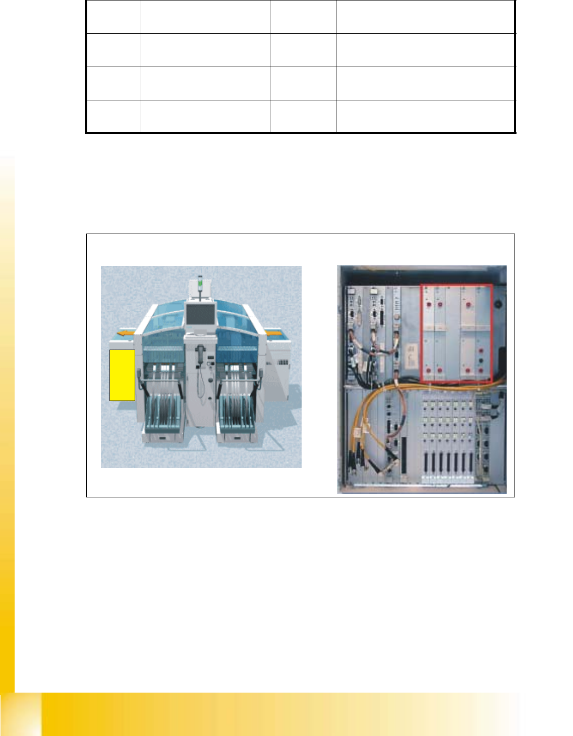
2.2 Control Cage
2.2.1 Power supply module
Fig. 2.2 - 1 Control Cageand power supply unit
After the main switch has been activated, the DC/DC converter in the control unit is supplied with
60 VDC from the power supply unit.
(1) +/- 12 VDC for the digital electronics
(2) +/-15 VDC for the analog electronics
(3) +24 VDC to supply the control circuits, relays, etc.
(4) +5 VDC / 20 A for the digital electronics in the individual sectors
(5) 50 VDC input for the power supply
(6) +5 VDC / 60 A for the digital electronics in the control unit
F8
fuse
PCB conveyor
1, 2
38 VDC against minus of rectifier V5.
F9
fuse
component table (logic)
1, 2
8 VDC against minus of rectifier V6.
F10
fuse
control unit
1, 2
52 VDC against minus of rectifier V7.
F11
fuse
in rush limiter
1, 2
30 VDC against minus of rectifier V8.
Left View (main operator controls) Power Supply modules
(1)(2) (3)
(4)
(5)
(6)
Student Guide HS-50 Advanced I 06/2002 Edition
2 Overview
11
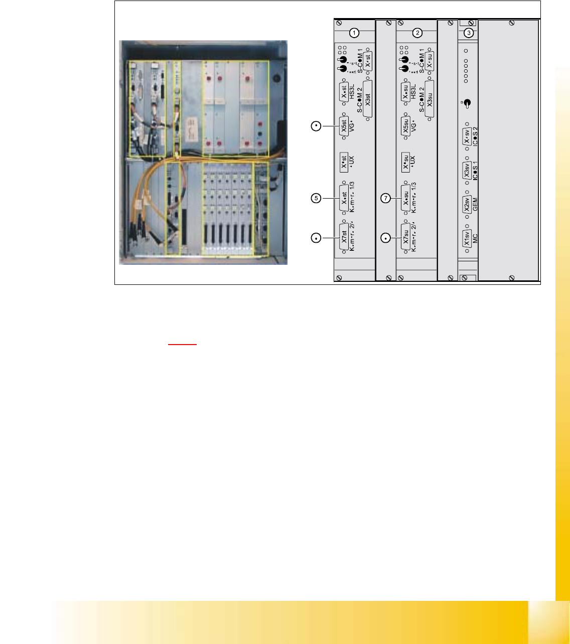
2.2.2 Vision SystemsControl Cage, Vision Sytems
The electronic image signals from components, PCB fiducials and feeder module fiducials can be
transferred from the vision analysis units via the video multiplexer to the two station monitors,
where they are used for measuring and testing purposes. 2
2
Fig. 2.2 - 2 Vision analysis units
Key to Fig. 2.2 - 2
(1) MVS 340 vision analysis unit, gantries 1 and 4
(2) MVS 340 vision analysis unit, gantries 2 and 3
(3) Video multiplexer
(4) Position of the control unit
(5) X6st: Component and PCB camera, gantry 1
(6) X7st: Component and PCB camera, gantry 4
(7) X6su: Component and PCB camera, gantry 2
(8) X7su: Component and PCB camera, gantry 3
(9) X5st: Image output (VGA) for plug X3sv (video multiplexer)
(10) X5su: Image output (VGA) for plug X4sv (video multiplexer)
The Vision systems analyze the camera images
06/2002 Edition Student Guide HS-50 Advanced I
2 Overview
12
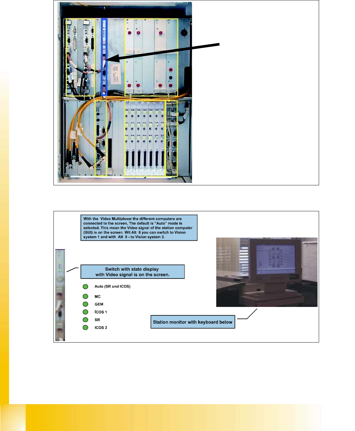
2.2.3 Video Multiplexer
Fig. 2.2 - 3 Control Cage, Video Multiplexer
Fig. 2.2 - 4 Video Multiplexer
The video multiplexer switches
the monitor on the various
computers