HS50_advance_level 1_20200522_221201 (1).pdf - 第411页
Editi on 06/2002 S tudent Guide HS - 50 Advance d I 1 1 Pneumat ic Cutter and Emp ty-T ap e Duct 24 NO TE: Only the prod uct v ers ion 03 holddo w ns are to be used f or version 04 cutters (= with tape deflector). The sp…

Student Guide HS-50 Advanced I Edition 06/2002
11 Pneumatic Cutter and Empty-Tape Duct
23
11.6.3 Exchanging the Stationary Blade and Movable Blade incl. Spacers
11.6.3.1 Removing the Old Blades incl. Spacers
WARNING
Wear thick protective gloves.
You might cut yourself on the blades and the tape deflector.
Never reach into the pneumatic cutter from below or into the empty-tape duct from above.
Make certain that no one can injure themselves on the dismantled blades standing next to the ma-
chine. 11
NOTE:
The stationary blade and the movable blade, including the spacers, must always be exchanged
as a set if both cutting edges are blunt.
The blades which are removed can be reground at the Siemens facility. 11
à Remove the cutter from the machine, as described in Section 11.6.1.
à Before any further disassembly, use 2 parallel clamps to fasten the dismantled cutter to a flat,
sturdy work bench by the cutter’s retaining brackets or four M6 socket hex head cap screws to
attach it tightly to the plate (Item no.: see Section 11.3)
-> see CAUTION in Section 11.6.10.
à Remove the stationary blade, as described in Section 11.6.2.
à Loosen the screws fastening the LH and RH cover plate holder over the movable blade (2
screws each, on outside left and right: see Fig. 11.4.2 -> 4) and fold back the long side of the
cover plate.
-> Do not damage the cables in this process.
à Loosen the screws fastening the left and right tape deflector holder above the movable blade
(two M4 screws each, on outside left and right: see Fig. 11.4.2 -> 7, 9).
Do not loosen the countersunk screws (see Fig. 11.4.2 -> 10).
à Remove the tape deflector holder (incl. cover plate and tape deflector) and set this unit down
carefully (with the tape deflector up).

Edition 06/2002 Student Guide HS-50 Advanced I
11 Pneumatic Cutter and Empty-Tape Duct
24
NOTE:
Only the product version 03 holddowns are to be used for version 04 cutters (= with tape deflector).
The spacers removed are always replaced by the new spacers included in the blade set.
Blades and spacers are attuned (= match). 11
à Remove the two holdowns and the spacers underneath them (see Fig. 11.4.2 -> 11).
à Holding the articulated joint with a size 10 open-end wrench (see Fig. 11.6.1 -> 3), loosen the
screws fastening the articulated joint in the movable blade (1 socket hex head cap screw each
at right and left, see Fig. 11.6.1 -> 4).
The screws are secured with Loctite no. 243, so considerable strength may be necessary.
à Use protective gloves and take hold of the stationary blade by its ends and lift it out of the cut-
ter.
11.6.3.2 Installing the New Blades and Matched Spacers
WARNING
Wear thick protective gloves.
You might cut yourself on the blades and the tape deflector.
Never reach into the pneumatic cutter from below or into the empty-tape duct from above. 11
NOTE
All parts must be clean before installing.
When the blades are delivered they have a very fine film of grease on them.
They are not to be treated with fat dissolving agents (risk that rust film may develop), nor are they
to be coated with more grease (risk that they may become dirty due to adhesion of solid
particles).
This would cause a detrimental effect on the movement of the movable blade. 11
à If the new blades are not clean, wipe them off very cautiously (protective gloves) on all sides
with a clean, carefully folded cloth.
-> Do not use any grease dissolving agents.
Student Guide HS-50 Advanced I Edition 06/2002
11 Pneumatic Cutter and Empty-Tape Duct
25
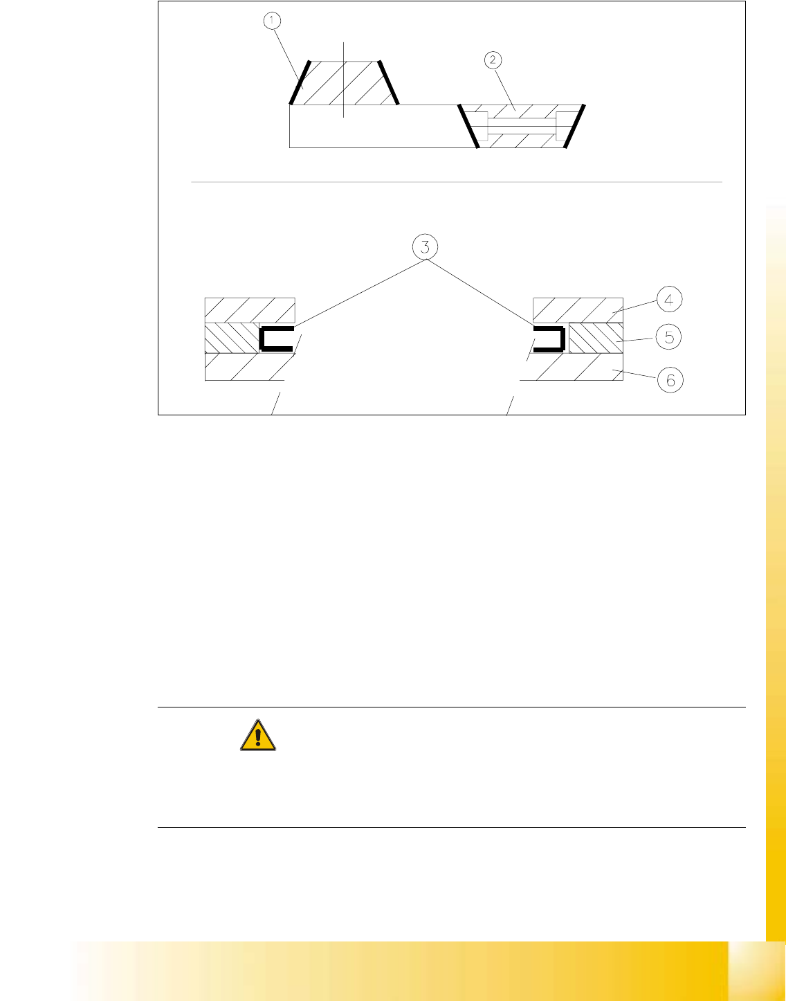
Fig. 11.6.2 Mounting New Blades, Mounting Position of the Blades, Slide Surfaces to be Greased
Key:
1. Stationary blade
2. Movable blade
3. Slide surfaces to be greased before installing the movable blade.
4. Holddown
5. Spacer
6. Contact surface
CAUTION
When installing new blades, place the blade so that the blade slope is in the correct rotational po-
sition (see Fig. 11.6.2).
Tighten the screws to the correct torque -> see Table, Fig. 11.4.2. 11
à Insert the movable blade into the cutter in the correct rotational position while pushing it into its
original mounting position.