HS50_advance_level 1_20200522_221201 (1).pdf - 第413页
Editi on 06/2002 S tudent Guide HS - 50 Advance d I 1 1 Pneumat ic Cutter and Emp ty-T ap e Duct 26 à A pply Loctite no . 243 (Item no. : see Section 11.3) on the two M4 sc r ews used to fas t en the ar- ticulated joint …
Student Guide HS-50 Advanced I Edition 06/2002
11 Pneumatic Cutter and Empty-Tape Duct
25
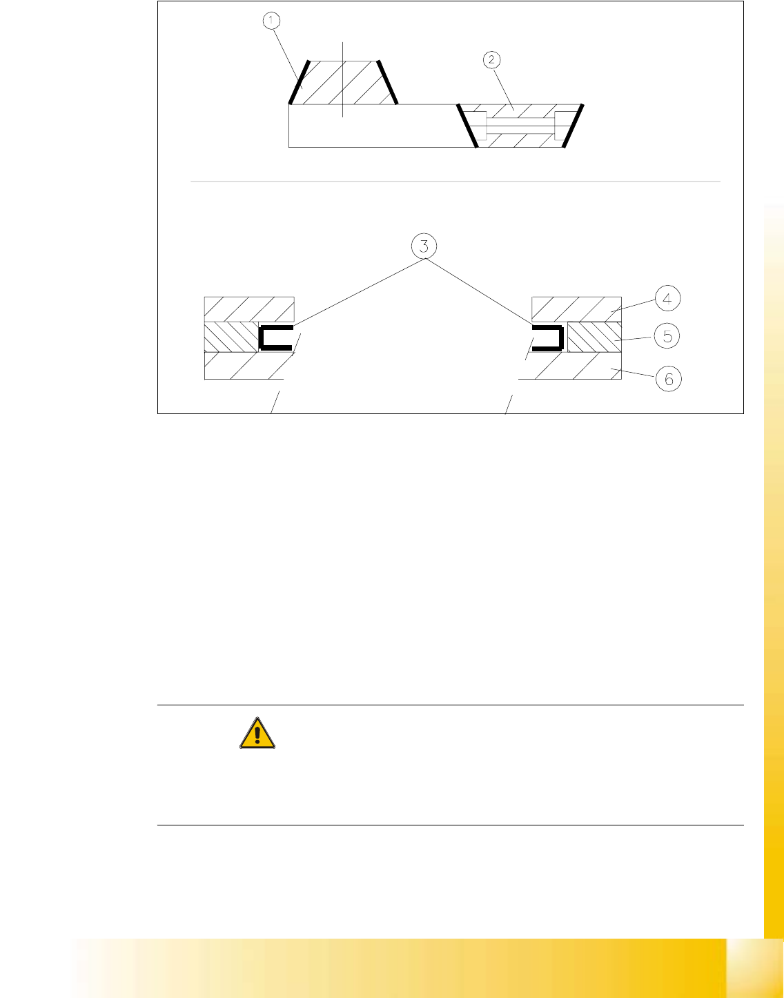
Fig. 11.6.2 Mounting New Blades, Mounting Position of the Blades, Slide Surfaces to be Greased
Key:
1. Stationary blade
2. Movable blade
3. Slide surfaces to be greased before installing the movable blade.
4. Holddown
5. Spacer
6. Contact surface
CAUTION
When installing new blades, place the blade so that the blade slope is in the correct rotational po-
sition (see Fig. 11.6.2).
Tighten the screws to the correct torque -> see Table, Fig. 11.4.2. 11
à Insert the movable blade into the cutter in the correct rotational position while pushing it into its
original mounting position.

Edition 06/2002 Student Guide HS-50 Advanced I
11 Pneumatic Cutter and Empty-Tape Duct
26
à Apply Loctite no. 243 (Item no.: see Section 11.3) on the two M4 screws used to fasten the ar-
ticulated joint in the movable blade (details: see Fig. 11.6.4 -> 7).
à Re-install these screws on the left and right in the movable blade.
NOTE:
Make certain that the midline / open-end wrench surface of the articulated joint is at right angles
to the slide surface of the movable blade (see Fig. 11.6.4 -> 5 and 6) and that the articulated joint
can slide in the slot (= prevents turning) in the movable blade. 11
à Using the size 10 open-end wrench to hold the appropriate articulated joint, tighten both
screws with the mentioned torque (see Table, Fig. 11.4.1)
à Place the 2 new spacers (Item no.: see Section 11.2) to the left and right of the movable blade
(see Fig. 11.4.2 ->11).
– Spacers and blades are attuned (= match).
à Grease the contact / slide surfaces for the movable blade exactly in the area shown in Fig.
11.6.2 -> 10 (Item no. of the grease: see Section 11.3).
-> Greasing the blades is not allowed.
à Place an adjustment plate (0.5 to 1.0 mm thick) on the left and right between spacer and the
face of the movable blade.
à Place the holddowns previously removed back on the new spacers.
-> The version 03 holddowns match the version 04 cutters (= with tape deflector).
à Re-install the previously removed deflector holder (= with tape deflector) and tighten the 4
socket hex head cap screws (see Fig. 11.4.2 -> 9), just hand-tight at first.
à Push the spacers (with inserted adjustment plate) toward the movable blade to the stop but not
until they exert pressure against it, otherwise it would no longer be possible to remove the ad-
justment plates.
– The maximum permissible gap is 1.0 mm.
à In this position, tighten the 4 screws on the tape deflector holders crosswise (torque: see Table
in Fig. 11.4.2).
à Remove the 2 adjustment plates.
à Insert the new stationary blade in the correct position (see Fig. 11.6.2) and tighten the 2 screws
(see Fig. 11.6.1 -> 4).
-> Tighten the screws to the correct torque -> see Table, Fig. 11.4.2.
à Using the feeler gauge, check the gap between tape deflector and movable blade (see detail
in Fig. 11.4.3) over the entire length and width of the blade:
à It must be possible to pull the 0.05 mm feeler gauge through it.
à It must be impossible to pull the 0.25 mm feeler gauge through.
11

Student Guide HS-50 Advanced I Edition 06/2002
11 Pneumatic Cutter and Empty-Tape Duct
27
f the gap is incorrect, check:
– Was an incorrect holddown (with version < 03) installed ?
The holddowns match the version 04 cutters (= with tape deflector).
– Wasn’t the blade, tape deflector, etc., cleaned before installation ?
If the gap is OK:
à Carefully fold the cover plate (with cover plate holders installed) back over the tape deflec-
tor.
à Make certain that the edges are parallel, then screw the cover plate holder to the cutter (two
M4 screws each (see Fig. 11.4.2 -> 7, 9):
-> Do not pinch or put strain on the cables.
à Install the cover plate on the stationary blade (4 screws M4, see Fig. 11.4.2 -> 12, 13).
à Remove the parallel clamps from the cutter or dismantle the cutter from the mounting plate.
à Mount the cutter in the machine, as described in Section 11.6.1.2.
à Install the empty-tape duct assembly and check the entire length of the gap between the
leading edge of the tape deflector and the “empty-tape baffle, inside", as described in Sec-
tion 11.6.8.
à Perform the appropriate “Final Steps” (see Section 11.6.11).