HS50_advance_level 1_20200522_221201 (1).pdf - 第416页
S tud ent Guid e HS-50 A dvanced I E dition 06/2 002 1 1 P neumatic Cutt er and Empty- T ape Du ct 29 Fig. 11.6. 3 R emovi ng and I n stal lin g the Sh or t-S tr o k e Cyli nder Ke y: 1. Short -stroke cylinders 1 an d 2 …

Edition 06/2002 Student Guide HS-50 Advanced I
11 Pneumatic Cutter and Empty-Tape Duct
28
11.6.4 Exchanging: Short-Stroke Cylinder and Articulated Joint on Left / Right
WARNING
Wear thick protective gloves.
You might cut yourself on the blades and the tape deflector.
Never reach into the pneumatic cutter from below or into the empty-tape duct from above. 11
11.6.4.1 Removing the Short-Stroke Cylinder / the Articulated Joint
à Remove the cutter from the machine, as described in Section 11.6.1.
à Perform all steps up to and including “...loosening the screws fastening the articulated joint” (in
this case only on the faulty short-stroke cylinder), as described in Section 11.6.2.1.
– The mounting position of the stationary blade (= right-hand end remains on the right) must
be restored during installation.
– The movable blade is left installed.
à Loosen the compressed air connections on the faulty short-stroke cylinder (see Fig. 11.6.3
-> 8).
à Using a fine-tip, water-insoluble marker, accurately mark the specified position of the proximity
switch on the faulty short-stroke cylinder.
à In addition, mark the allocation of the proximity switches to the faulty short-stroke cylinder (po-
sition front/back).
à Loosen the screws fastening the two inductive proximity switches to the short-stroke cylinder
(1 screw each: see Fig. 11.6.3 -> 4, 5).
à Loosen the screws fastening the faulty short-stroke cylinder (2 screws: see Fig. 11.6.3 -> 2)
and remove the cylinder, incl. the articulated joint screwed into it.
à Dismantle articulated joint from the cylinder by turning the open-end wrench (width across flats
10) on the surface indicated in Fig. 11.6.4 -> 3).
NOTE:
The threaded pin is secured with Loctite no. 243, so it takes somewhat more strength to loosen it.11
Student Guide HS-50 Advanced I Edition 06/2002
11 Pneumatic Cutter and Empty-Tape Duct
29
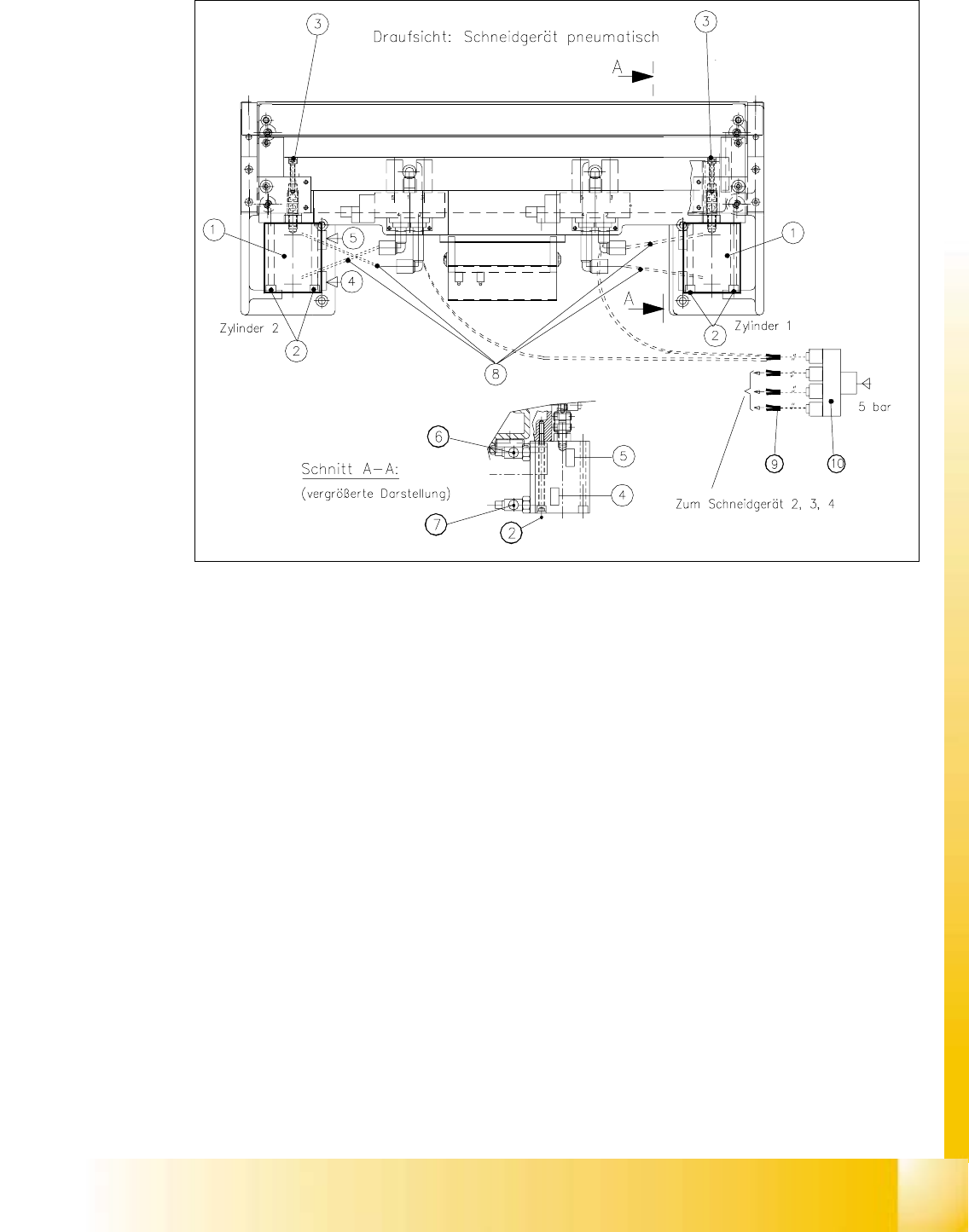
Fig. 11.6.3 Removing and Installing the Short-Stroke Cylinder
Key:
1. Short-stroke cylinders 1 and 2
2. Screws fastening the short-stroke cylinders: 2 socket hex head cap screws each, M5 x 65
3. Screws fastening the articulated joint (see also Fig. 11.6.4)
4. Proximity switch (for position cylinder moved in). Fastener: 1 cross-slotted screw
5. Proximity switch (for position cylinder moved out). Fastener: 1 cross-slotted screw
6. One-way restrictor (for running cylinder out)
7. One-way restrictor (for running cylinder in)
8. Allocation of the compressed air connections, air hoses
9. Y-socket union (in the cable pit)
10. Multiple-Y-distributor on the safety valve (5 bar from compressed air unit)

Edition 06/2002 Student Guide HS-50 Advanced I
11 Pneumatic Cutter and Empty-Tape Duct
30
11.6.4.2 Installing the Short-Stroke Cylinder / the Articulated Joint
WARNING
You might cut yourself on the blades and the tape deflector. 11
CAUTION
Tighten the screws to the correct torque -> see Table, Fig. 11.4.2. 11
11
11
Key to Fig. 11.6.4 (right):
1. Short-stroke cylinder (1 or 2)
2. Articulated joint (complete)
3. Wrench surface for disassembling the articulated joint
4. Secure articulated joint thread with Loctite no. 243
5. Open-end wrench surface of articulated joint
6. Slide surface of the movable blade
7. Screw fastening the articulated joint to the movable blade:
one M4 x 24 DIN 912 socket hex head cap screw each, strength 12.9,
secured with Loctite no. 243
8. Movable blade with slot to prevent the articulated joint from turning