HS50_advance_level 1_20200522_221201 (1).pdf - 第418页
S tud ent Guid e HS-50 A dvanced I E dition 06/2 002 1 1 P neumatic Cutt er and Empty- T ape Du ct 31 Fig . 1 1.6.4 Remo ving Art iculate d Jo int, Insta ll ing I t on N ew M ast er Cyl inde r an d Bon ding It in Pl ace …

Edition 06/2002 Student Guide HS-50 Advanced I
11 Pneumatic Cutter and Empty-Tape Duct
30
11.6.4.2 Installing the Short-Stroke Cylinder / the Articulated Joint
WARNING
You might cut yourself on the blades and the tape deflector. 11
CAUTION
Tighten the screws to the correct torque -> see Table, Fig. 11.4.2. 11
11
11
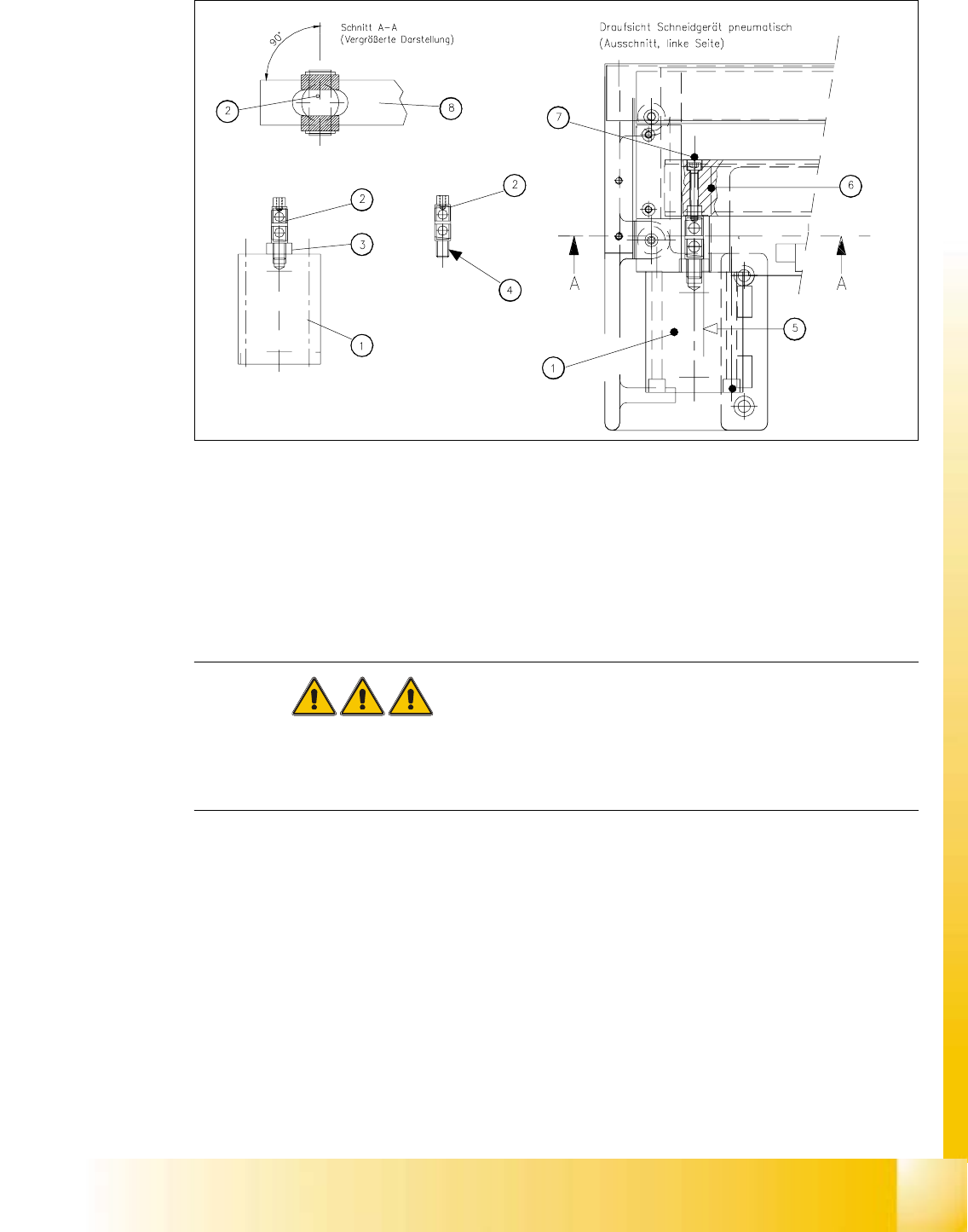
Key to Fig. 11.6.4 (right):
1. Short-stroke cylinder (1 or 2)
2. Articulated joint (complete)
3. Wrench surface for disassembling the articulated joint
4. Secure articulated joint thread with Loctite no. 243
5. Open-end wrench surface of articulated joint
6. Slide surface of the movable blade
7. Screw fastening the articulated joint to the movable blade:
one M4 x 24 DIN 912 socket hex head cap screw each, strength 12.9,
secured with Loctite no. 243
8. Movable blade with slot to prevent the articulated joint from turning
Student Guide HS-50 Advanced I Edition 06/2002
11 Pneumatic Cutter and Empty-Tape Duct
31
Fig. 11.6.4 Removing Articulated Joint, Installing It on New Master Cylinder and Bonding It in Place
à If the articulated joint is damaged, use a (complete) new one (Item no.: see Section 11.2) or
clean the residues of Loctite from the thread of the existing articulated joint pin.
à Apply a small amount of Loctite no. 243 (Item no.: see Section 11.3) to the thread.
à Take note of the following WARNING. If the enamel on the one-way restrictor is damaged use
a new "short-stroke cylinder assembly HS-50".
DANGER
One-way restrictors are not to be set on the machine. This is only permitted at the factory.
For this reason the replacement short-stroke cylinder must always be installed, together with the
new, already adjusted restrictors attached to it. 11
à Screw the threaded pin into the short-stroke cylinder. If necessary use a new "short-stroke cyl-
inder assembly for HS-50" (Item no.: see Section 11.2).
à Turn the articulated joint into the mounting position (see Fig. 11.6.4: diagram on left) and
tighten the articulated joint against the wrench surface.
Once the cylinder is installed, the slot in the movable blade prevents the articulated joint from
turning.
à Copy the exact mounting position of the proximity switch from the old short-stroke cylinder to
the new one (feeler gauge, fine-tip marker).
à Having thus prepared the cylinder, install it, complete with one-way restrictors and incl. the ar-
ticulated joint, on the cutter in the correct rotational position.

Edition 06/2002 Student Guide HS-50 Advanced I
11 Pneumatic Cutter and Empty-Tape Duct
32
NOTE:
Make certain that the midline / open-end wrench surface of the articulated joint is at right angles
to the slide surface of the movable blade (see Fig. 11.6.4 -> 5 and 6) and so that the articulated
joint can slide smoothly in the slot (= prevents turning) in the movable blade. 11
à Fasten the cylinder in this position with 2 screws each (see Fig. 11.6.3 -> 2).
NOTE:
Installing the proximity switch precisely (exactly on, not next to or over the marks) will save you the
need to make a subsequent time-consuming correction (see below "If the switching point of the
proximity switch is not correct..."). 11
à Install the proximity switch (Item no.: see Section 11.2) precisely in the position you marked on
the short-stroke cylinder with the permanent marker (see Fig. 11.6.3 -> 4, 5).
à Connect the compressed air hoses to the one-way restrictor on the cylinder in the correct allo-
cation.
-> Allocation: see Fig. 11.6.3 -> 6, 7, 8).
à For the following steps proceed, as described in Section 11.6.3.2
- to fasten the movable blade on the articulated joint,
- to adjust the spacers for the movable blade,
- to install the holders for the tape deflector (incl. cover plate and tape deflector),
- to install the stationary blade.
à Re-install the empty-tape duct on the machine frame (2 screws each on LH and RH, see Fig.
11.4.1 -> 6, 9).
à Check the gap between the leading edge of the tape deflector and the “empty-tape baffle, in-
side", as described in Section 11.6.8.
à Check the switching points of the proximity switches, as described in Section 11.6.7.
NOTE:
If the tapes are not cut correctly even though the switching points are set properly and the short-
stroke cylinder has been exchanged, complete with the one-way restrictor, the cause of the prob-
lem may be:
Compressed air level incorrect, compressed air connection or Y-socket union leaking, blade in
poor condition, solenoid valve faulty, break in the drive circuit of solenoid valve. 11
à Perform the appropriate “Final Steps” (see Section 11.6.11).