HS50_advance_level 1_20200522_221201 (1).pdf - 第419页
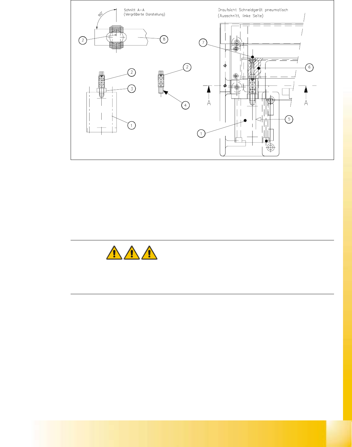
Editi on 06/2002 S tudent Guide HS - 50 Advance d I 1 1 Pneumat ic Cutter and Emp ty-T ap e Duct 32 NO TE: Make ce r tain t hat the midline / open-end wrenc h surface of the a rticulated joint is at ri ght angles to the …
Student Guide HS-50 Advanced I Edition 06/2002
11 Pneumatic Cutter and Empty-Tape Duct
31
Fig. 11.6.4 Removing Articulated Joint, Installing It on New Master Cylinder and Bonding It in Place
à If the articulated joint is damaged, use a (complete) new one (Item no.: see Section 11.2) or
clean the residues of Loctite from the thread of the existing articulated joint pin.
à Apply a small amount of Loctite no. 243 (Item no.: see Section 11.3) to the thread.
à Take note of the following WARNING. If the enamel on the one-way restrictor is damaged use
a new "short-stroke cylinder assembly HS-50".
DANGER
One-way restrictors are not to be set on the machine. This is only permitted at the factory.
For this reason the replacement short-stroke cylinder must always be installed, together with the
new, already adjusted restrictors attached to it. 11
à Screw the threaded pin into the short-stroke cylinder. If necessary use a new "short-stroke cyl-
inder assembly for HS-50" (Item no.: see Section 11.2).
à Turn the articulated joint into the mounting position (see Fig. 11.6.4: diagram on left) and
tighten the articulated joint against the wrench surface.
Once the cylinder is installed, the slot in the movable blade prevents the articulated joint from
turning.
à Copy the exact mounting position of the proximity switch from the old short-stroke cylinder to
the new one (feeler gauge, fine-tip marker).
à Having thus prepared the cylinder, install it, complete with one-way restrictors and incl. the ar-
ticulated joint, on the cutter in the correct rotational position.

Edition 06/2002 Student Guide HS-50 Advanced I
11 Pneumatic Cutter and Empty-Tape Duct
32
NOTE:
Make certain that the midline / open-end wrench surface of the articulated joint is at right angles
to the slide surface of the movable blade (see Fig. 11.6.4 -> 5 and 6) and so that the articulated
joint can slide smoothly in the slot (= prevents turning) in the movable blade. 11
à Fasten the cylinder in this position with 2 screws each (see Fig. 11.6.3 -> 2).
NOTE:
Installing the proximity switch precisely (exactly on, not next to or over the marks) will save you the
need to make a subsequent time-consuming correction (see below "If the switching point of the
proximity switch is not correct..."). 11
à Install the proximity switch (Item no.: see Section 11.2) precisely in the position you marked on
the short-stroke cylinder with the permanent marker (see Fig. 11.6.3 -> 4, 5).
à Connect the compressed air hoses to the one-way restrictor on the cylinder in the correct allo-
cation.
-> Allocation: see Fig. 11.6.3 -> 6, 7, 8).
à For the following steps proceed, as described in Section 11.6.3.2
- to fasten the movable blade on the articulated joint,
- to adjust the spacers for the movable blade,
- to install the holders for the tape deflector (incl. cover plate and tape deflector),
- to install the stationary blade.
à Re-install the empty-tape duct on the machine frame (2 screws each on LH and RH, see Fig.
11.4.1 -> 6, 9).
à Check the gap between the leading edge of the tape deflector and the “empty-tape baffle, in-
side", as described in Section 11.6.8.
à Check the switching points of the proximity switches, as described in Section 11.6.7.
NOTE:
If the tapes are not cut correctly even though the switching points are set properly and the short-
stroke cylinder has been exchanged, complete with the one-way restrictor, the cause of the prob-
lem may be:
Compressed air level incorrect, compressed air connection or Y-socket union leaking, blade in
poor condition, solenoid valve faulty, break in the drive circuit of solenoid valve. 11
à Perform the appropriate “Final Steps” (see Section 11.6.11).
Student Guide HS-50 Advanced I Edition 06/2002
11 Pneumatic Cutter and Empty-Tape Duct
33
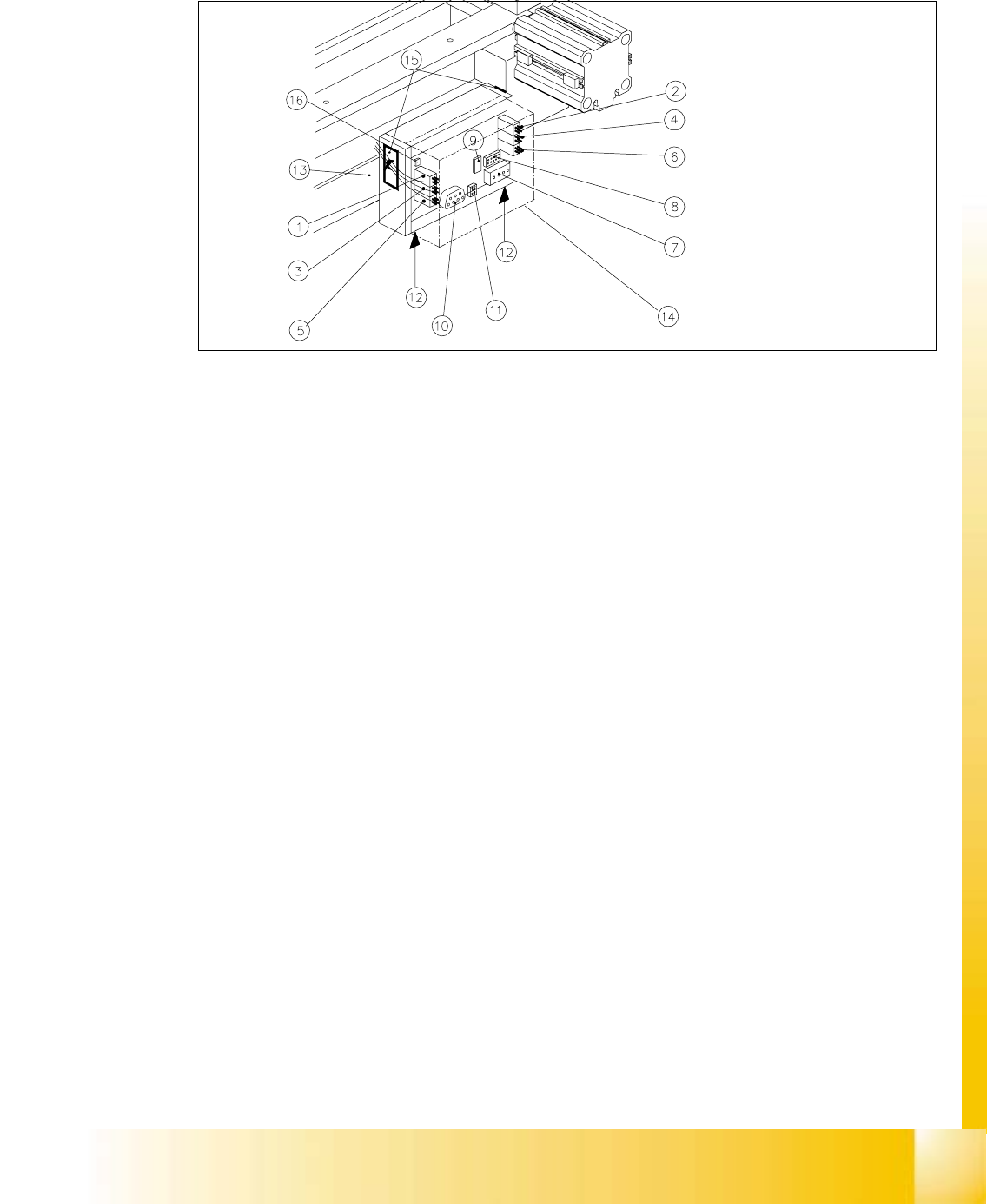
11.6.5 Exchanging the Control Unit
Fig. 11.6.5 Exchanging the Control Unit, Allocation of the Plug-and-Socket Connections
Key:
1. Drive of solenoid valve for cylinder 2 (left)
2. Drive of solenoid valve for cylinder 1 (right)
3. to the proximity switch on cylinder 2, FRONT
4. to the proximity switch on cylinder 1, FRONT
5. to the proximity switch on cylinder 2, BACK
6. to the proximity switch on cylinder 1, BACK
7. Cutter power supply (only busy on S-23 and F5)
8. Drive of cutter (only busy on S-23 and F5)
9. Service plug (to be used exclusively by Siemens)
10. CAN bus
11. Power supply
12. Spring-mounted elements to disconnect the control board box
13. Support bar
14. Cover
15. Fixing pedestal adhesive type (LH and RH) with cable tie
Relieve tensile stress on cable/plug-and-socket connections.
16.Coding plug