HS50_advance_level 1_20200522_221201 (1).pdf - 第42页
06/2002 E dition Studen t Guide H S-50 Advance d I 2 Ov erview 12 2.2. 3 Video Multip lexer F ig. 2. 2 - 3 Co ntr ol C age , Vid e o Mu lti plex er F ig. 2. 2 - 4 Video M ulti ple xer The vid eo mul ti p lexer switches t…
Student Guide HS-50 Advanced I 06/2002 Edition
2 Overview
11
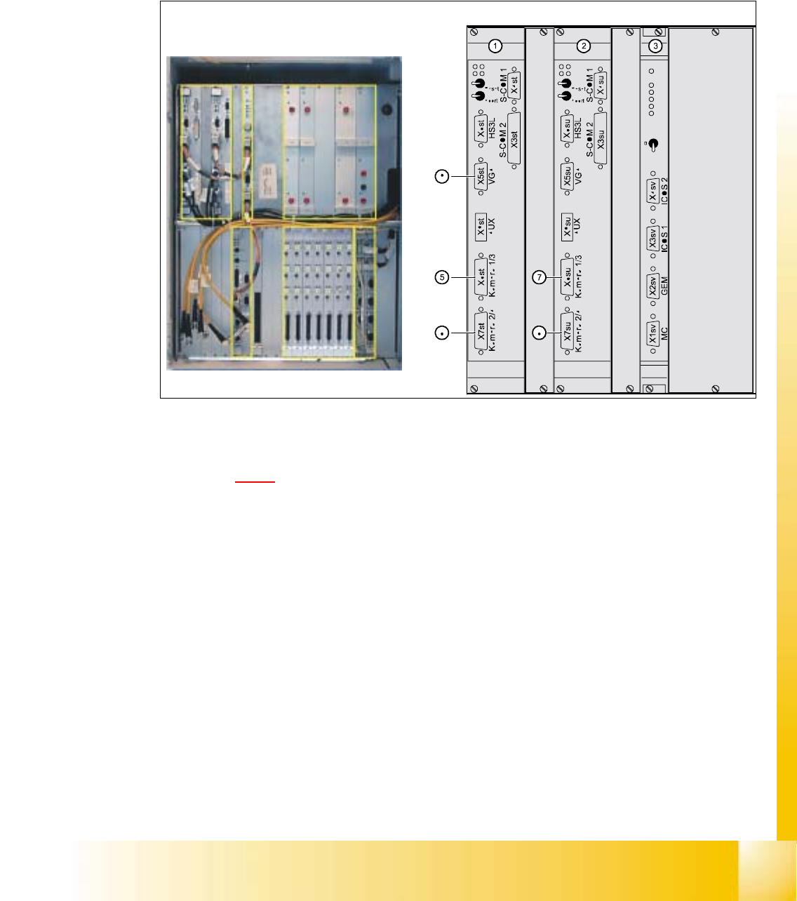
2.2.2 Vision SystemsControl Cage, Vision Sytems
The electronic image signals from components, PCB fiducials and feeder module fiducials can be
transferred from the vision analysis units via the video multiplexer to the two station monitors,
where they are used for measuring and testing purposes. 2
2
Fig. 2.2 - 2 Vision analysis units
Key to Fig. 2.2 - 2
(1) MVS 340 vision analysis unit, gantries 1 and 4
(2) MVS 340 vision analysis unit, gantries 2 and 3
(3) Video multiplexer
(4) Position of the control unit
(5) X6st: Component and PCB camera, gantry 1
(6) X7st: Component and PCB camera, gantry 4
(7) X6su: Component and PCB camera, gantry 2
(8) X7su: Component and PCB camera, gantry 3
(9) X5st: Image output (VGA) for plug X3sv (video multiplexer)
(10) X5su: Image output (VGA) for plug X4sv (video multiplexer)
The Vision systems analyze the camera images
06/2002 Edition Student Guide HS-50 Advanced I
2 Overview
12
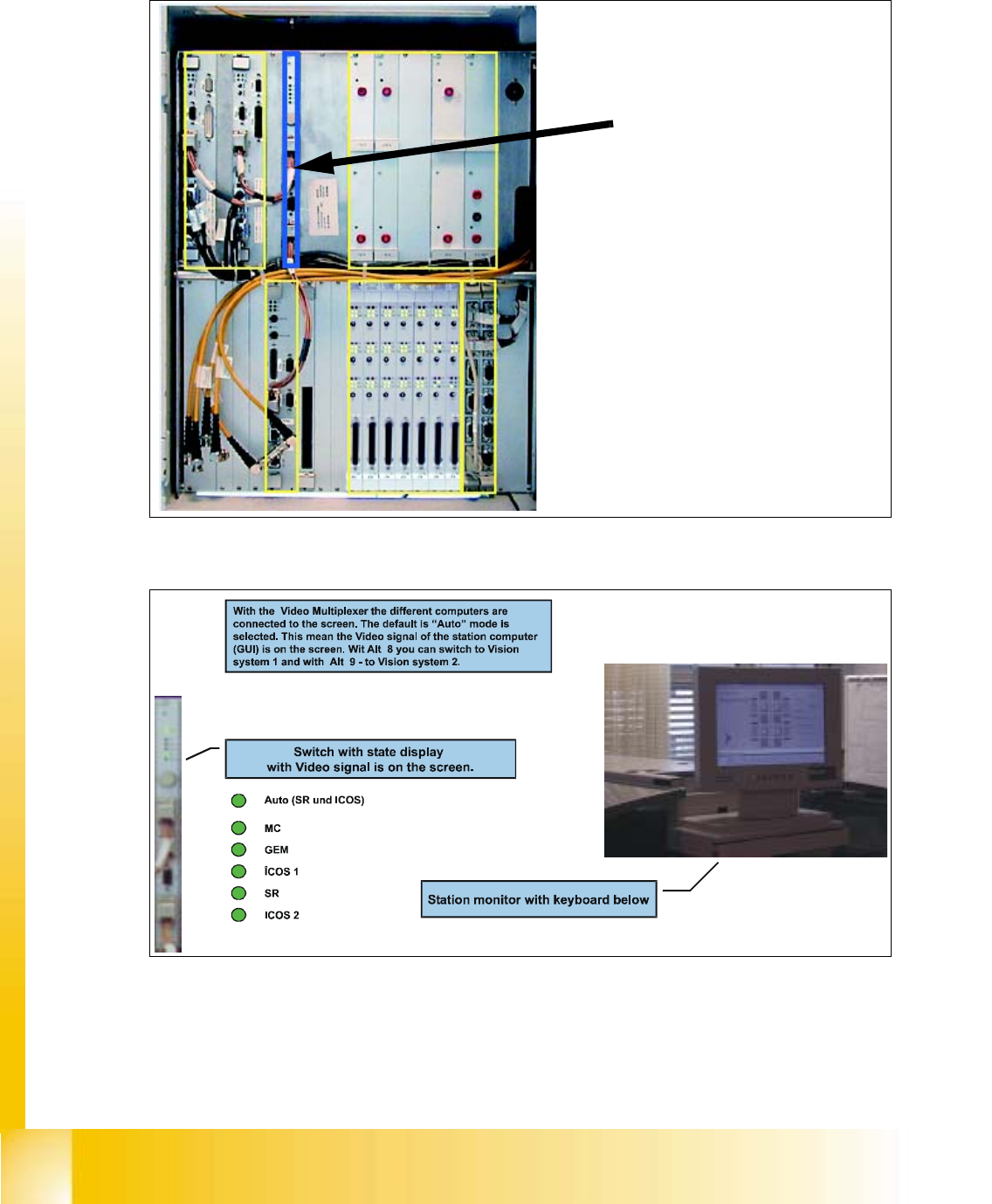
2.2.3 Video Multiplexer
Fig. 2.2 - 3 Control Cage, Video Multiplexer
Fig. 2.2 - 4 Video Multiplexer
The video multiplexer switches
the monitor on the various
computers
Student Guide HS-50 Advanced I 06/2002 Edition
2 Overview
13
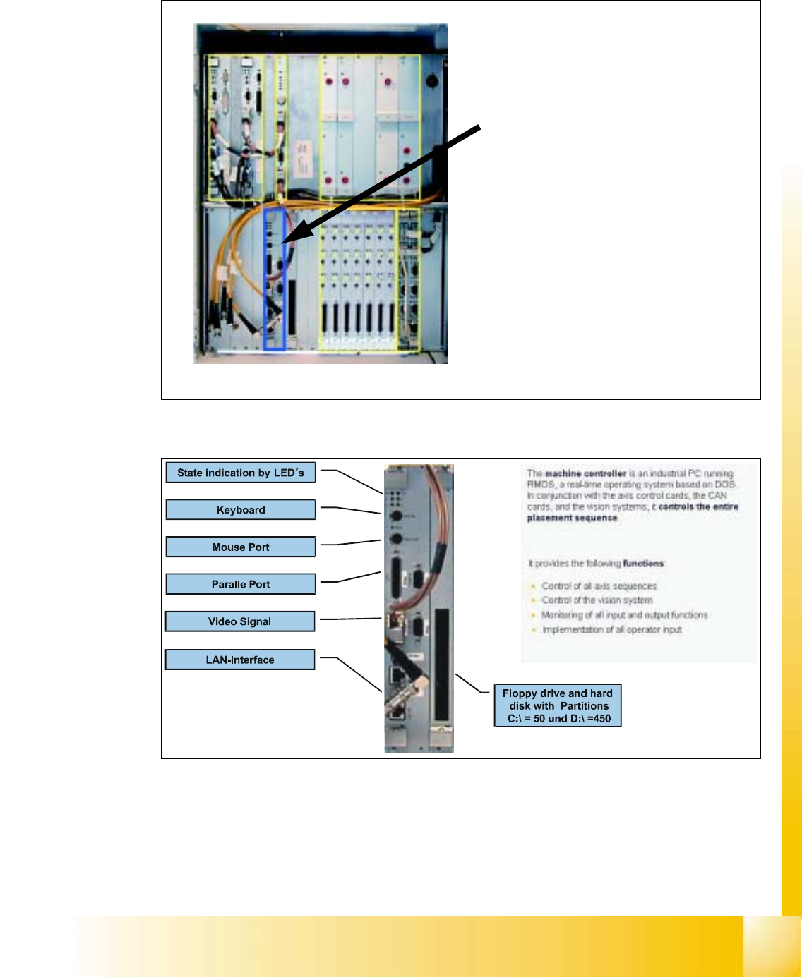
2.2.4 Machine Controller M54
Fig. 2.2 - 5 Control cage, machine controller
Fig. 2.2 - 6 Machine Controller M54
The machine controller is the central
control unit of the placement machine