HS50_advance_level 1_20200522_221201 (1).pdf - 第424页
S tud ent Guid e HS-50 A dvanced I E dition 06/2 002 1 1 P neumatic Cutt er and Empty- T ape Du ct 37 If th e cable o f the s olenoid va lve is fau lty: à Ca refully und o the corresponding cab le t ie (left or r ight) o…
Edition 06/2002 Student Guide HS-50 Advanced I
11 Pneumatic Cutter and Empty-Tape Duct
36
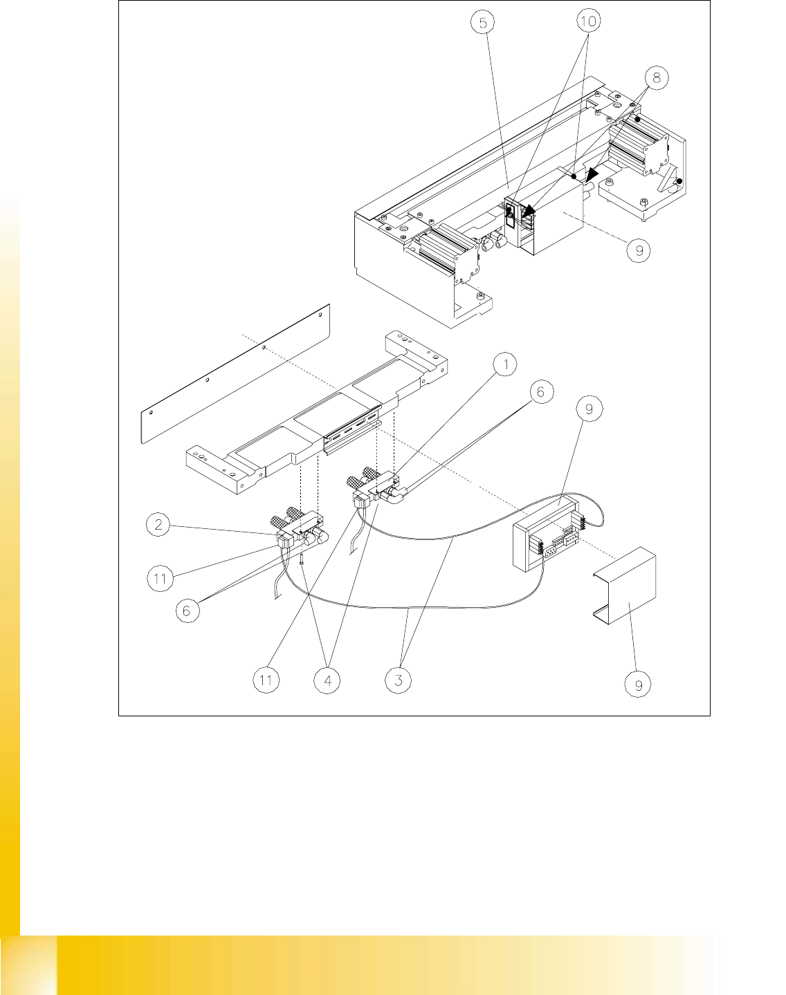
Fig. 11.6.6 Exchanging the Solenoid Valve

Student Guide HS-50 Advanced I Edition 06/2002
11 Pneumatic Cutter and Empty-Tape Duct
37
If the cable of the solenoid valve is faulty:
à Carefully undo the corresponding cable tie (left or right) on the outside of the control board
box (see Fig. 11.6.6 -> 10).
-> Do not damage the cables in this process.
à Remove the cover from the control board (see Fig. 11.6.6 -> 9).
à Unplug the plug-and-socket connection of the cable "Control board for tape cutter - valve"
of the appropriate solenoid valve on the control board (see Fig. 11.6.5 -> 1, 2).
à Loosen the plug-and-sockeet connection of the cable "Control board for tape cutter - valve"
of the appropriate solenoid valve (see Fig. 11.6.5).
à Take the cover off the cable pit (see Fig. 11.6.6 -> 5).
à Remove the cable and run the new cable "Control board for tape cutter - valve" (Item no.:
see Section 11.2). Push the excess lengths of cable into the cable pit.
à Make the plug-and-socket connection on the board (see Fig. 11.6.5) and on the solenoid
valve with correct allocation (see Fig. 11.6.6).
à Place the cover back on the control board (see Fig. 11.6.6 -> 9).
à Install the cover on the cable pit (see Fig. 11.6.6 -> 5).
à Use a cable tie to fasten the cables running to LH and/or RH side of the cable pit to the fixing
pedestal (on control board box).
The strain on the cable / plug-and-socket connections must be relieved (see Fig. 11.6.6 ->
8).
à Perform the appropriate “Final Steps” (see Section 11.6.11).
If the solenoid valve is faulty:
à Undo the 2 compressed air connections on the one-way restrictors at the faulty solenoid
valve (see Fig. 11.6.6 -> 1, 2, 6).
à Unplug the plug-and-socket connection of the cable "Control board tape cutter - valve"
on the faulty solenoid valve (see Fig. 11.6.6 -> 11).
à Undo the screws fastening the faulty solenoid valve (2 M3 screws: see Fig. 11.6.6 -> 4) and
remove the solenoid valve.
à Mount the new solenoid valve (Item no.: see Section 11.2) in the correct position, as shown
in Fig. 11.6.6. Make the plug-and-socket connection at the solenoid valve:
-> Tighten the screws to the correct torque -> see Table, Fig. 11.4.2.
-> The strain on the cable must be relieved (see Fig. 11.6.6 -> 8).
à Mount the short-stroke cylinder compressed air connections to the one-way restrictors on
the solenoid valve with the correct allocation (see Fig. 11.6.3 -> 6, 7, 8).
à Perform the appropriate “Final Steps” (see Section 11.6.11).

Edition 06/2002 Student Guide HS-50 Advanced I
11 Pneumatic Cutter and Empty-Tape Duct
38
11.6.7 Exchanging the Inductive Proximity Switch
WARNING
You might cut yourself on the blades and the tape deflector.
Never reach into the pneumatic cutter from below or into the empty-tape duct from above. 11
11.6.7.1 Removing the Proximity Switch
The cutter remains installed in the machine.
à Turn the machine and then the compressed air ON.
à Disconnect the movable component changeover table from the machine and move it out of the
machine.
à Turn the machine OFF, disconnect the machine from the mains and turn off the flow of com-
pressed air at the compressed air. Actuate the needle valve on the compressed air unit to bleed
the compressed air lines (see DANGER text in Section 11.1).
à Remove the cover from the control board (see Fig. 11.6.5 -> 14).
à Carefully undo the corresponding cable tie (left or right) on the outside of the control board box
(see Fig. 11.6.5 -> 10).
-> Do not damage the cables in the process.
à Using a fine-tip permanent marker, precisely mark on the short-stroke cylinder the specified
position of the proximity switch that is to be exchanged.
à Disengage the plug-and-socket connection of the faulty proximity switch on the control board
(allocation: see Fig. 11.6.5).
If you loosen more than one of the plug-and-socket connection simultaneously, mark the allo-
cation.
à Take the cover off the cable pit (see Fig. 11.6.6 -> 5).
à Undo the screw fastening the proximity switch to the short-stroke cylinder (1 screw: see Fig.
11.6.3 -> 4 or 5) and remove the proximity switch including the cable.