HS50_advance_level 1_20200522_221201 (1).pdf - 第45页
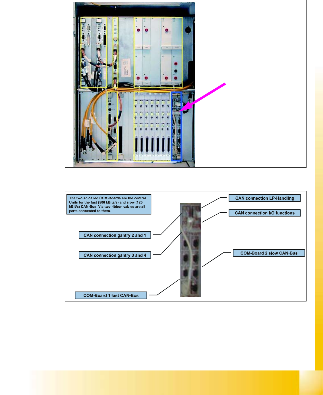
Studen t Guide HS-50 A dvanced I 06/200 2 Edition 2 Overview 15 2.2. 6 CAN-Bus Contro ller Fig. 2.2 - 9 Cont ro l ca ge, CAN -Bus co ntrol ler Fig. 2.2 - 10 CAN-B us Cont roll er The c ommunicat ion m odules provide an i…
06/2002 Edition Student Guide HS-50 Advanced I
2 Overview
14
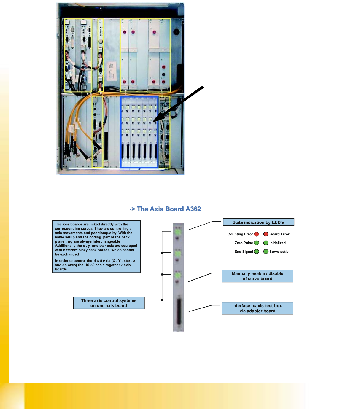
2.2.5 Axes Boards A362
Fig. 2.2 - 7 Control cage, Axes boards
Fig. 2.2 - 8 Axis Board A362
The controller for the individual axes
is located in the axes control boards
Student Guide HS-50 Advanced I 06/2002 Edition
2 Overview
15
2.2.6 CAN-Bus Controller
Fig. 2.2 - 9 Control cage, CAN-Bus controller
Fig. 2.2 - 10 CAN-Bus Controller
The communication modules
provide an interface to the
CAN-Bus
06/2002 Edition Student Guide HS-50 Advanced I
2 Overview
16
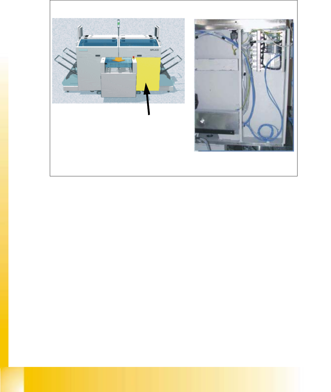
2.3 Sector 3
Fig. 2.3 - 1 Sector 3, CAN bus adapter
CAN bus adapterPCB output side
Sector 3
Sector 3 contains the CAN bus
adapter for the changeover table of gantry 3