HS50_advance_level 1_20200522_221201 (1).pdf - 第54页
06/2002 E dition Studen t Guide H S-50 Advance d I 2 Ov erview 24 2. 7 Sect or 1 F ig. 2. 7 - 1 S ecto r1 2.8 St ation Com puter F ig. 2. 8 - 1 Stati on com pu te r PC B inpu t side S e ctor 1 Sector 1 contains CAN bus a…
Student Guide HS-50 Advanced I 06/2002 Edition
2 Overview
23
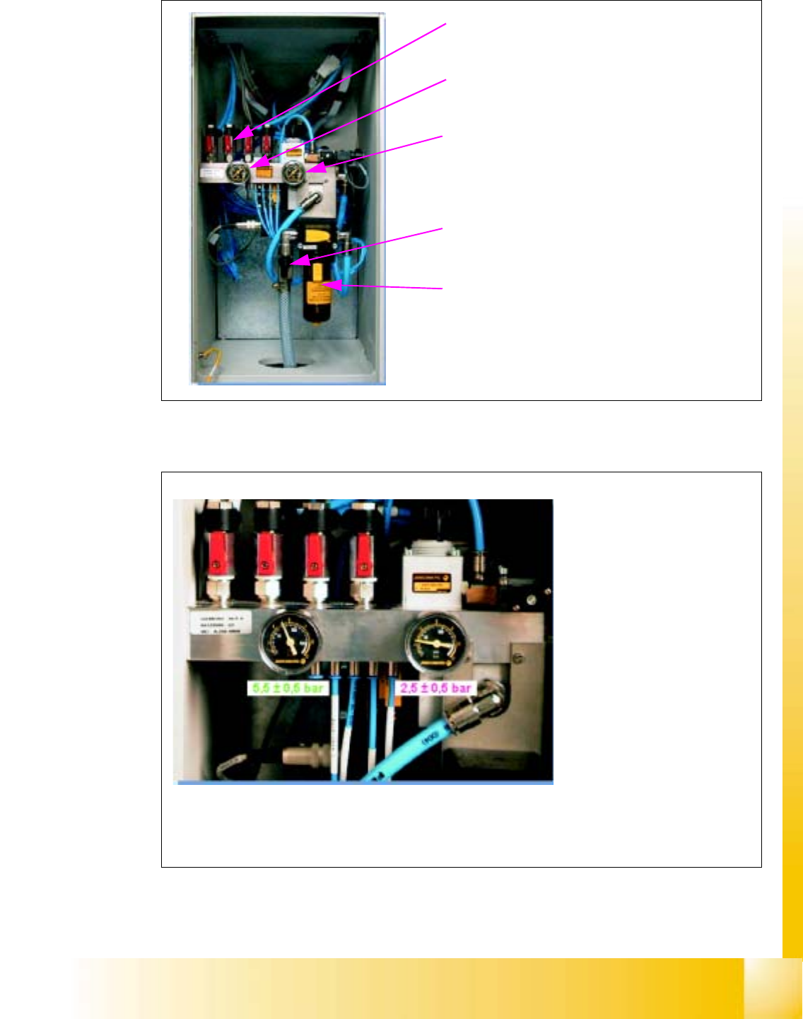
2.6.1 Elements of the pneumatic cage
Fig. 2.6 - 2 Pneumatic cage, Elements of the pneumatik unit
2.6.2 Pressure values
Fig. 2.6 - 3 Pneumatic cage, Pressure values
Stopcocks for gantries (G1, G2, G3, G4)
Manometer (preset supply pressure)
Manometer (manually set supply for pressure)
Main cock for compressed air supply
Filter
After the machine has been
switched on, the valve block in
the pneumatic unit provides the
following supply pressures:
5,5 +/-0,5bar for
- the pneumatic cutting devices
- the PCB stoppers
- The nozzle changers
- the component changeover
tables
- the vacuum generators of the
gantries
2,5 +/- 0,5 bar for
- the bulk case feeder
06/2002 Edition Student Guide HS-50 Advanced I
2 Overview
24
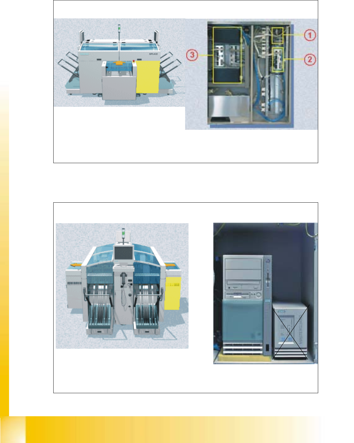
2.7 Sector 1
Fig. 2.7 - 1 Sector1
2.8 Station Computer
Fig. 2.8 - 1 Station computer
PCB input side Sector 1
Sector 1 contains CAN bus adapter (1) for the changeover table of gantry 1, an additional SLIO
for the optional nozzle changers (2), and the conveyor control unit (3)
One of the main funktions of the station computer is to
provide a graphical user interface for operating the ma-
chine. It also acts as a communication interface between the Line computer and the machine
controller
Left view (main operator controls) Station computer
Student Guide HS-50 Advanced I 06/2002 Edition
2 Overview
25
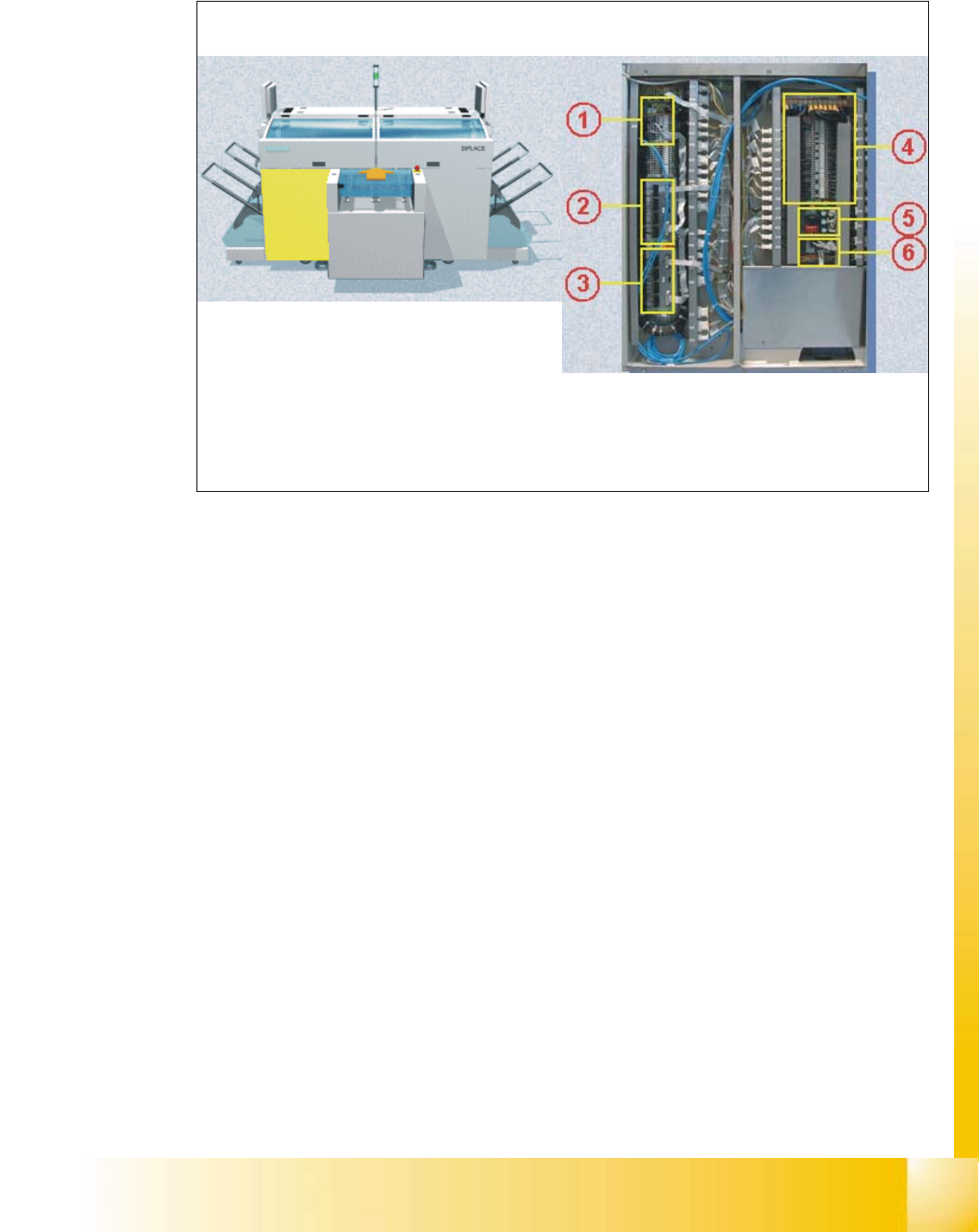
2.9 Sector 4
Fig. 2.9 - 1 Sector 4
Sector 4 contains the CAN bus adapter (1) for the changeover table of gantry 4, SLIO’s for the
safety circuit (2) and the first nozzle changer (3) among others, the main distributor (4), the
power supply unit for the step motors (5), and the illumination and flash distributor(6).
PCB input side Sector 4