HS50_advance_level 1_20200522_221201 (1).pdf - 第551页
06/2002 Edition S tudent Gui de HS- 50 Advanced I 20 App endix 24 20.4.4 .2 T esting the Head Boa rd Functions The functions of the head board a re used to test the respective p lacement head. Normally , the test is perf…

Student Guide HS-50 Advanced I 06/2002 Edition
20 Appendix
23
20.4.4 Common Program Related Problems
20.4.4.1 Testing and monitoring the status of the head board functions
On each gantry mounted above the revolver head is the interconnection board which is also
known as the head board 550. This PCB is used to transmit signals associated with the revolver
head, down through the ribbon cables to the various control elements.
Some of these functions are transmitted via the CANBUS system and it is possible to monitor the
status some of these elements using the LEDs fitted to the PCB. The next pages describe what
each of the LED’s indicate and how using the Sitest program it is possible to test the functions that
the LEDs monitor.
Also transmitted via the CANBUS are the signals from the vacuum measurement PCB. This func-
tion can also be tested in Sitest as well as the normal Single Functions menu in the operational
software. A description on how to perform these tests and how to interperate the result is given in
the following pages.
Error Message: Recovery:
The placement offsets are the
same for all positions.
The programmed x/y-values of the fiducials are incorrect.
Compare with CAD-data! Fiducial has not been centered cor-
rectly during the fiducial teaching. Test the fiducial in the func-
tion fiducial teaching! If a multiple board is only measured by 2
or 3 fiducials the problem can be wrong offsets of the single
boards. Check CAD-Data or program fiducial measurement
for every single board! If the line or subline is only composed
of one 80S or 80F-machine, the problem is possibly the offset
between RV-camera and PCB-camera of gantry 1. Calibrate
machine!! The screen printing process of solder paste is inac-
curate.
Offsets are constant at a sta-
tion but vary from one PCB to
the next. The offsets for one
PCB are even different from
station to station.
Fiducial recognition problems. The individual stations detect
the fiducial centers at different locations. Test the fiducial in the
function fiducial teaching again!
Component related prob-
lems:
Wrong nozzle.GF-data needs modification. For instance, illu-
mination, contrast, measurement modes, nozzle, camera
type, special handling, dimensions. Wrong placement posi-
tion; check with original cad data at first!
06/2002 Edition Student Guide HS-50 Advanced I
20 Appendix
24
20.4.4.2 Testing the Head Board Functions
The functions of the head board are used to test the respective placement head. Normally, the test
is performed with the aid of the "Head continuous run" function (see display "RV head functions").
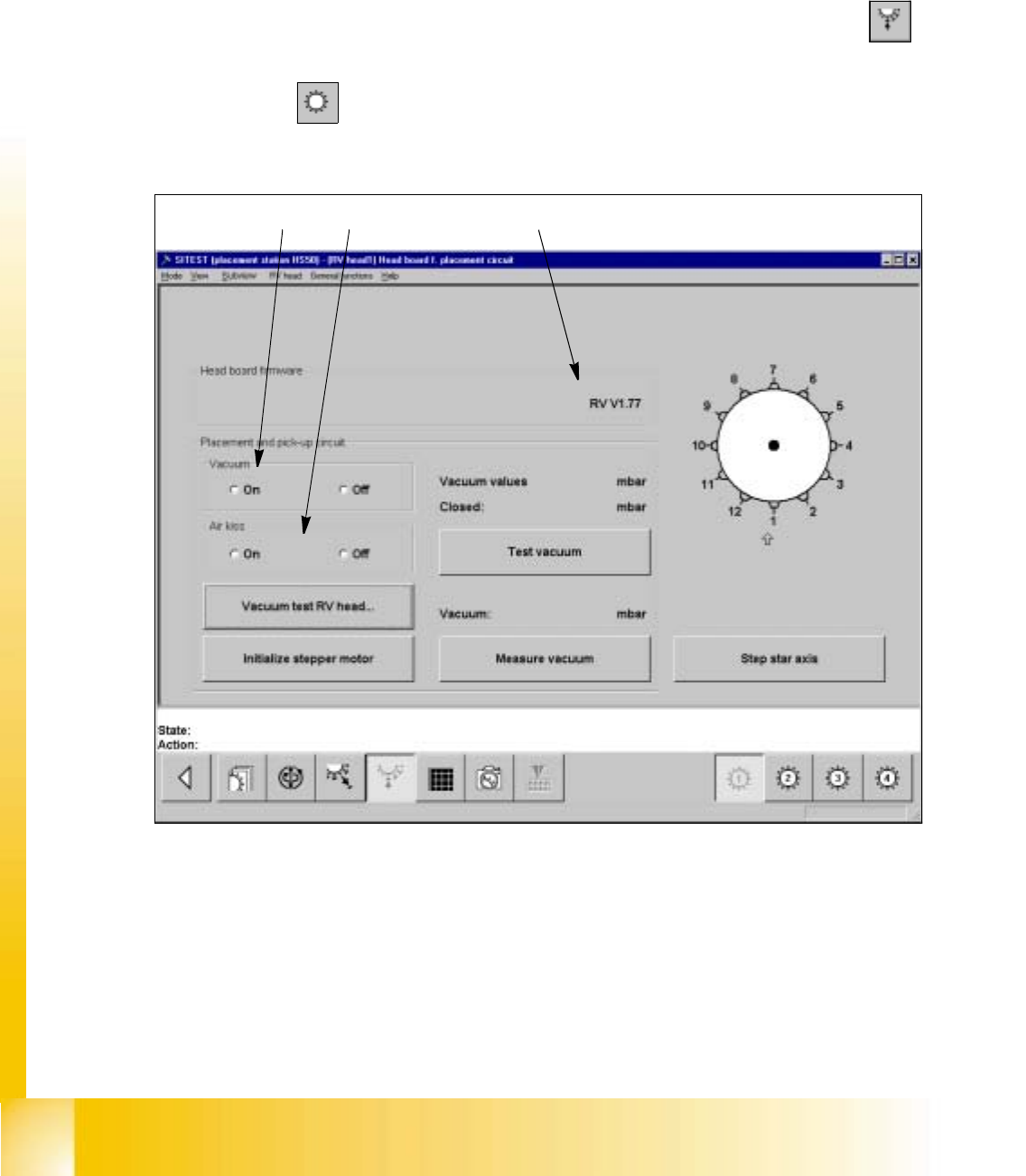
20.4.4.3 Functions of the RV Head in the Placement and Pick-Up Circuits
– If you wish to test the head functions in the placement and pick-up circuits, click on the
icon in
the "RV head" display to switch to the "Head board RV head, placement and pick-up cir-
cuit".
Fig. 20.4 - 1 "Head board RV head, placement and pick-up circuit" Display
Key:
a to switch the vacuum on/off
s to switch the air-kiss function at the placement station on/off
d version number of the firmware
12
3

Student Guide HS-50 Advanced I 06/2002 Edition
20 Appendix
25
– To switch the vacuum on/off, activate the appropriate radio button in the "Vacuum" field.
– To switch the air-kiss function on/off, activate the appropriate radio button in the "Air kiss"
field.
NOTE
Prior to the execution of the functions "Step star axis" and "Vacuum test RV head" described
below, a head reference run must have been performed on the RV head. 20
– To index the star, continue to click on the Step star axis button until the number of the de-
sired (center) sleeve is displayed above the arrow.
– To measure the vacuum values of all nozzles with the vacuum both switched on and off,
click on the Vacuum test RV head button. The measured values are displayed in a dialog
box.
– Close the dialog box by clicking on OK.
– To move the stepper motor into neutral position (starting position), click on the Initialize
stepper motor button.
– To check the vacuum, click on the Test vacuum button.
The values measured with the nozzle both open and closed, are displayed above the but-
ton.
– To measure the current vacuum values in the placement and pick-up circuit, click on the
Measure vacuum button. The measured value is displayed above the button.