HS50_advance_level 1_20200522_221201 (1).pdf - 第56页
06/2002 E dition Studen t Guide H S-50 Advance d I 2 Ov erview 26 2. 10 PCB T rans port 2.10.1 T ranp o rt se t up F ig. 2. 10 - 1 T ra ns por t sy s tem The H S-50 is divided in to two pro cessing area s: - Processing A…
Student Guide HS-50 Advanced I 06/2002 Edition
2 Overview
25
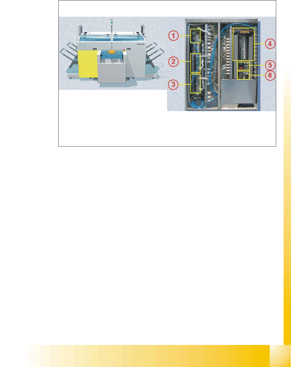
2.9 Sector 4
Fig. 2.9 - 1 Sector 4
Sector 4 contains the CAN bus adapter (1) for the changeover table of gantry 4, SLIO’s for the
safety circuit (2) and the first nozzle changer (3) among others, the main distributor (4), the
power supply unit for the step motors (5), and the illumination and flash distributor(6).
PCB input side Sector 4
06/2002 Edition Student Guide HS-50 Advanced I
2 Overview
26
2.10 PCB Transport
2.10.1 Tranport set up
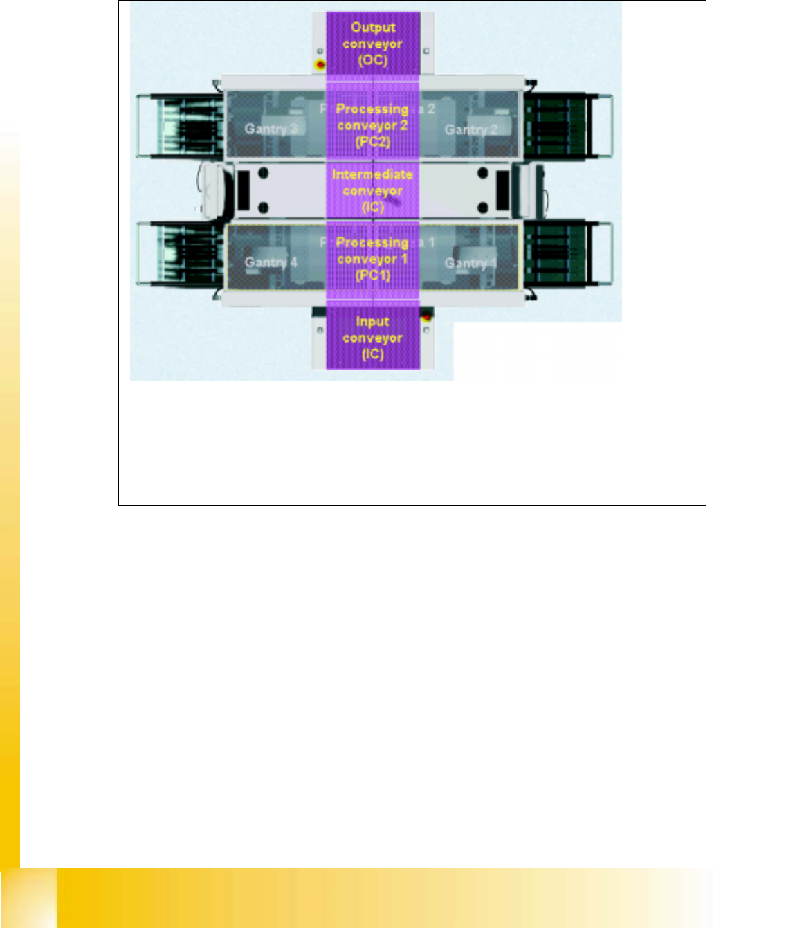
Fig. 2.10 - 1 Transport system
The HS-50 is divided into two processing areas:
- Processing Area 1 with gantries 1 and 4
- Processing Area 2 with gantries 2 and 3
The conveyor belt is also divided into a number of sections
– Input conveyor belt
– Processing conveyor belt 1
– Intermediate conveyor belt
– Processing conveyor belt 2
– Output conveyor belt
Student Guide HS-50 Advanced I 06/2002 Edition
2 Overview
27
2.10.2 Single and dual Transport Systems
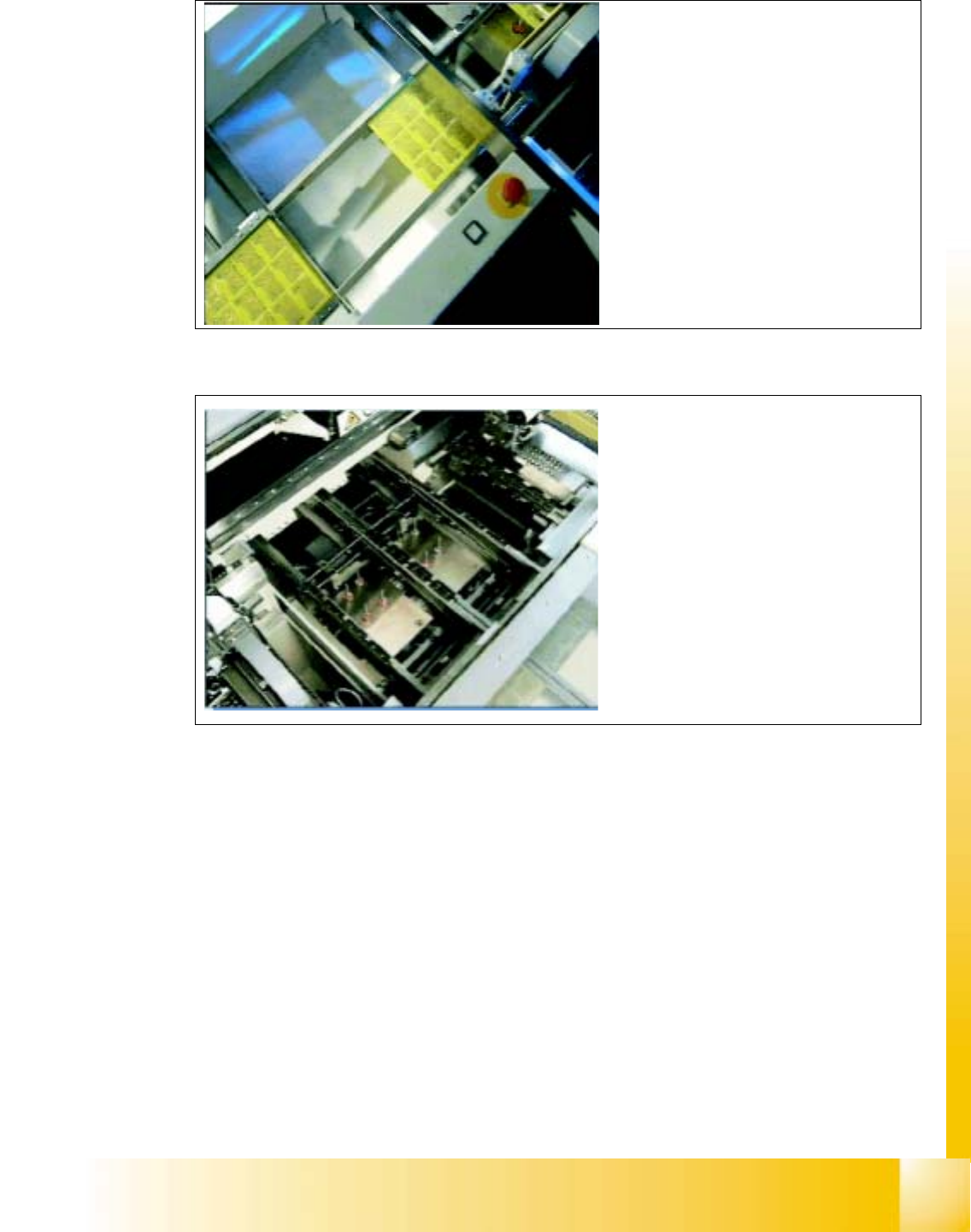
Fig. 2.10 - 2 Single or dual conveyor
Fig. 2.10 - 3 Conveyor system
Depending on the configuration, the
HS-50 have single or dual PCB con-
veyor.
This can be adjusted to suit different
PCB wdths by a motor, either using
menu functions on the station or by
means of automatic width adjustment on
the line computer
A dual conveyor allows for a
considerable increase in throughput,
as non productive transport times are
reduced by means of the alternate
(asynchronous) transport of two PCBs
though the placement machine.
Thus, while the first PCB can be trans-
ported onward and a new PCB loaded.