HS50_advance_level 1_20200522_221201 (1).pdf - 第561页
06/2002 Edition S tudent Gui de HS- 50 Advanced I 20 App endix 34 – If you w ish to i nform your self o f the stat e of the bit s of a gi v en inpu t po rt gr oup, acti vat e the corr espondi ng radi o b utton asso ciate…
Student Guide HS-50 Advanced I 06/2002 Edition
20 Appendix
33
20.4.6 Testing Input / Output Functions
The following pages describe how it is possible to check the status of the inputs to the I/O cards
and how to set and test outputs. Following the description are pages that detail the I/O port and
bit assignments and their interconnection points in the left hand terminal strip. Here it is possible
to use a multimeter when troubleshooting to monitor the status of the hard wire signals to and from
the control elements. This helps to determine the source to a problem i.e. Whether it is a control
problem from the I/O card or a hard wire problem associated with the control element.
20.4.6.1 In-/Output Functions
The functions described in the following serve to selectively interrogate and activate individual bits
of the input and output cards of the SIPLACE machines and the wafflepack changer (only input
card).
Inputs 20
20
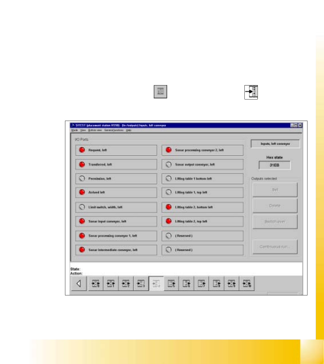
– In the main view click on the icon and then (if required) the icon to reach the
"Inputs" display.
20
Fig. 20.4 - 8 "Inputs" Display

06/2002 Edition Student Guide HS-50 Advanced I
20 Appendix
34
– If you wish to inform yourself of the state of the bits of a given input port group, activate the
corresponding radio button associated with the desired port by clicking on it.
The function of each bit contained in the selected port is displayed next to the "Port" field.
Next to each function the symbol of an LED is displayed whose color changes from gray to
red once the state(s) of the individual bit(s) has (have) been read and displayed in the "Hex
state" field.
NOTE
The uppermost LED symbol applies to bit "0", the lowermost to bit "7".
If the LED symbol is displayed in red, the state of the bit is "1" (active).
If the LED symbol is displayed in gray, the state of the bit is "0" (inactive). 20
Student Guide HS-50 Advanced I 06/2002 Edition
20 Appendix
35
Outputs 20
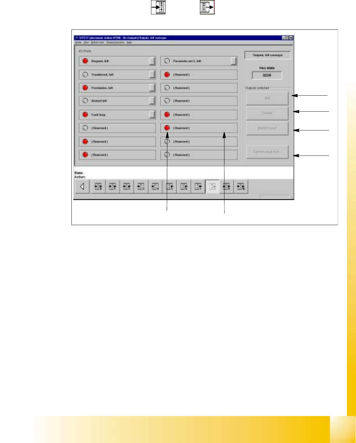
– In the "Inputs" display click on the icon to switch to the "Outputs" display.
Fig. 20.4 - 9 "Outputs" Display
Key:
a to set the selected bits
s to reset the selected bits
d to invert the current state
f to convert the state of the selected bits in the continuous run
g selected bit (output)
h LED symbol
– Activate the appropriate radio button of the port containing the output group you wish to test.
– Click on the check boxes next to the function descriptions of the outputs you wish to test,
or click directly on the function descriptions.
– Click on the button indicating the desired function. The selected function will be carried out.
1
2
3
4
5
6