HS50_advance_level 1_20200522_221201 (1).pdf - 第60页
06/2002 E dition Studen t Guide H S-50 Advance d I 2 Ov erview 30 2.12.2 Coordi nate S ystem F ig. 2. 12 - 2 Co or dina te sys tem 2.12.3 The HS-50 is a four gantry m achin e with AC d rives F ig. 2. 12 - 3 T he Y - a nd…
Student Guide HS-50 Advanced I 06/2002 Edition
2 Overview
29
Fig. 2.11 - 2 Changeover table, connector
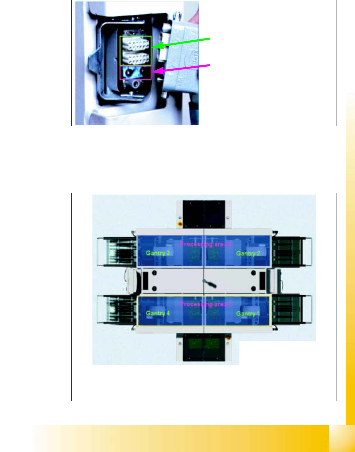
2.12 Gantry
2.12.1 Gantries and placement areas
Fig. 2.12 - 1 Gantries and placement areas
Power, control signals
and
compressed air
are supplied via a shared plug connection
The HS-50 is divided into two processing areas:
Processing area 1 with gantries 1 and 4
Processing area 2 with gantries 2 and 3
06/2002 Edition Student Guide HS-50 Advanced I
2 Overview
30
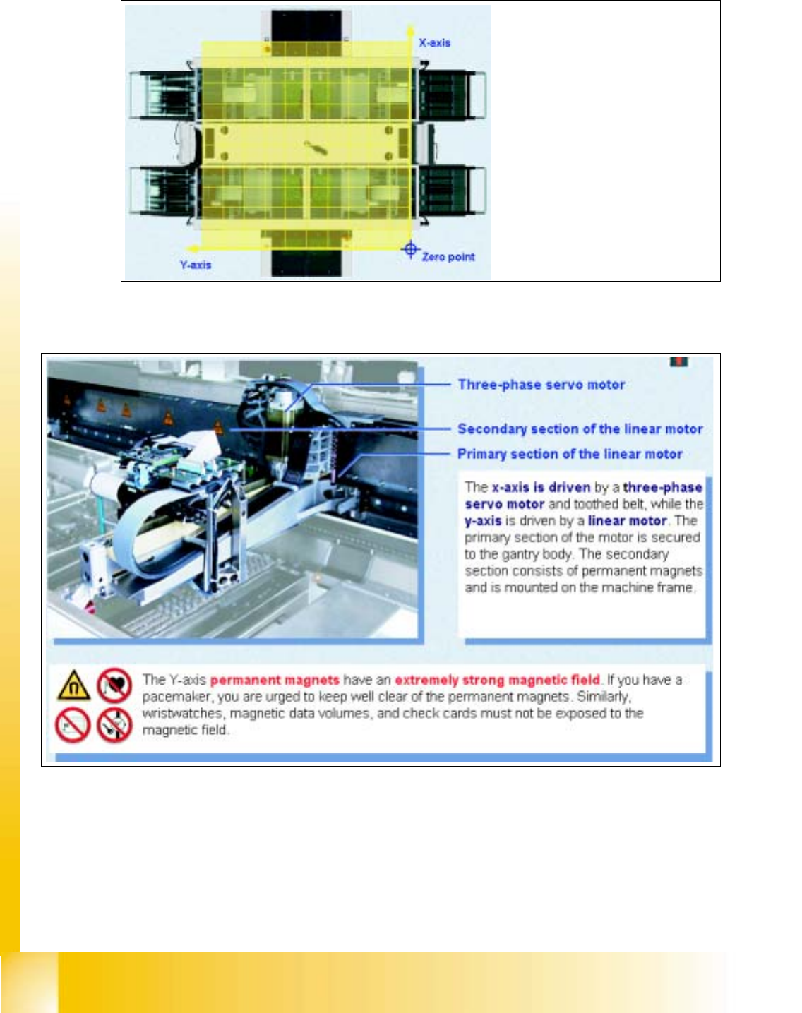
2.12.2 Coordinate System
Fig. 2.12 - 2 Coordinate system
2.12.3 The HS-50 is a four gantry machine with AC drives
Fig. 2.12 - 3 The Y- and X-axes
The zero point of the coordinate
system is located outside the ma-
chine in order to avoid negative
coordinates
Student Guide HS-50 Advanced I 06/2002 Edition
2 Overview
31
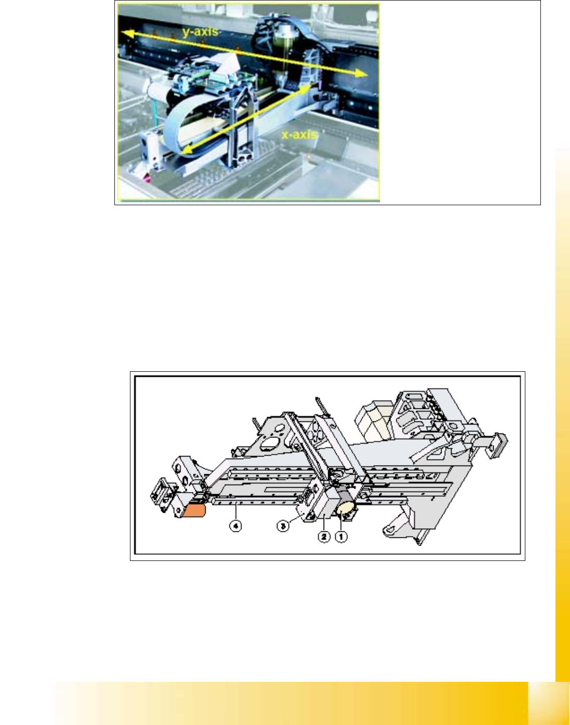
Fig. 2.12 - 4 The Y- and X-axes
2.12.4 PCB Camera
The PCB vision module uses fiducials on the PCBs to determine:
– the position of the PCB, its rotation angle, and the PCB delay.
The PCB vision module also uses fiducials on the feeder modules to determine the exact pick-up
position of components, which is particularly important for small components.
Fig. 2.12 - 5 PCB camera under the gantry
a PCB-camera with optics and illumination
s Camera amplifier
d Head holder
f Gantry
The gantry consists of an
X-axis
and a
Y-axis