HS50_advance_level 1_20200522_221201 (1).pdf - 第61页
Studen t Guide HS-50 A dvanced I 06/200 2 Edition 2 Overview 31 Fig. 2.12 - 4 The Y - and X -axes 2.12.4 PCB Camera The PCB v ision module uses fiducials on the PCBs to determine: – the position of the PCB, it s rotation…
06/2002 Edition Student Guide HS-50 Advanced I
2 Overview
30
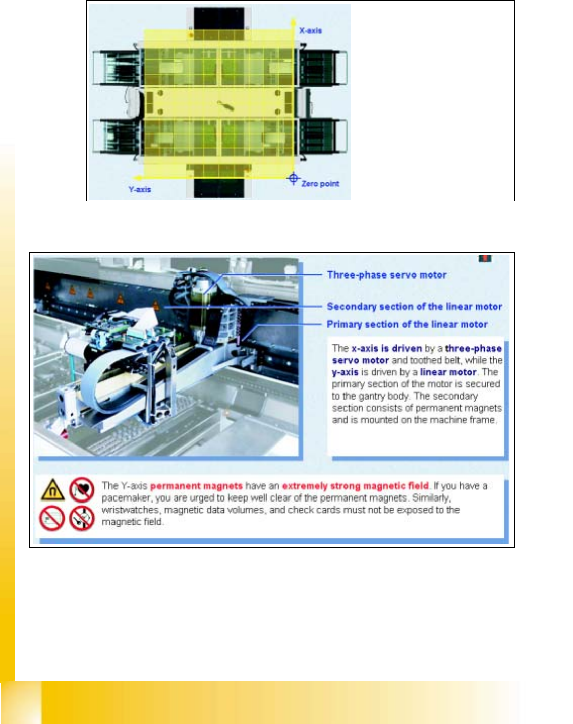
2.12.2 Coordinate System
Fig. 2.12 - 2 Coordinate system
2.12.3 The HS-50 is a four gantry machine with AC drives
Fig. 2.12 - 3 The Y- and X-axes
The zero point of the coordinate
system is located outside the ma-
chine in order to avoid negative
coordinates
Student Guide HS-50 Advanced I 06/2002 Edition
2 Overview
31
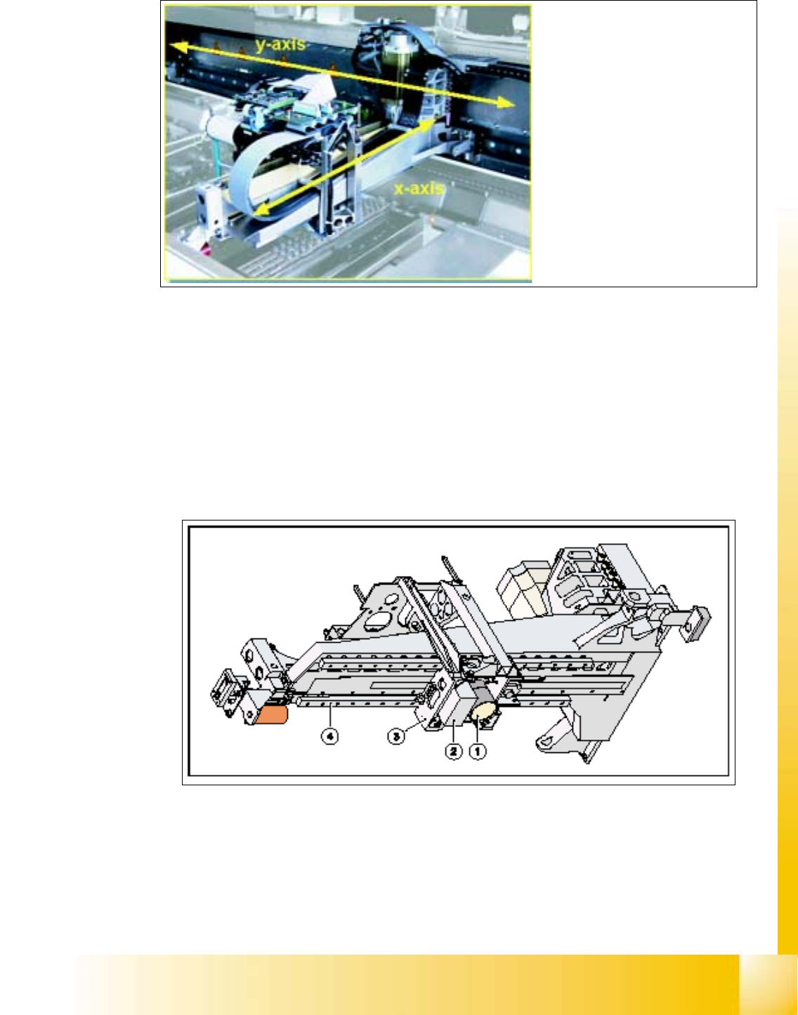
Fig. 2.12 - 4 The Y- and X-axes
2.12.4 PCB Camera
The PCB vision module uses fiducials on the PCBs to determine:
– the position of the PCB, its rotation angle, and the PCB delay.
The PCB vision module also uses fiducials on the feeder modules to determine the exact pick-up
position of components, which is particularly important for small components.
Fig. 2.12 - 5 PCB camera under the gantry
a PCB-camera with optics and illumination
s Camera amplifier
d Head holder
f Gantry
The gantry consists of an
X-axis
and a
Y-axis
06/2002 Edition Student Guide HS-50 Advanced I
2 Overview
32
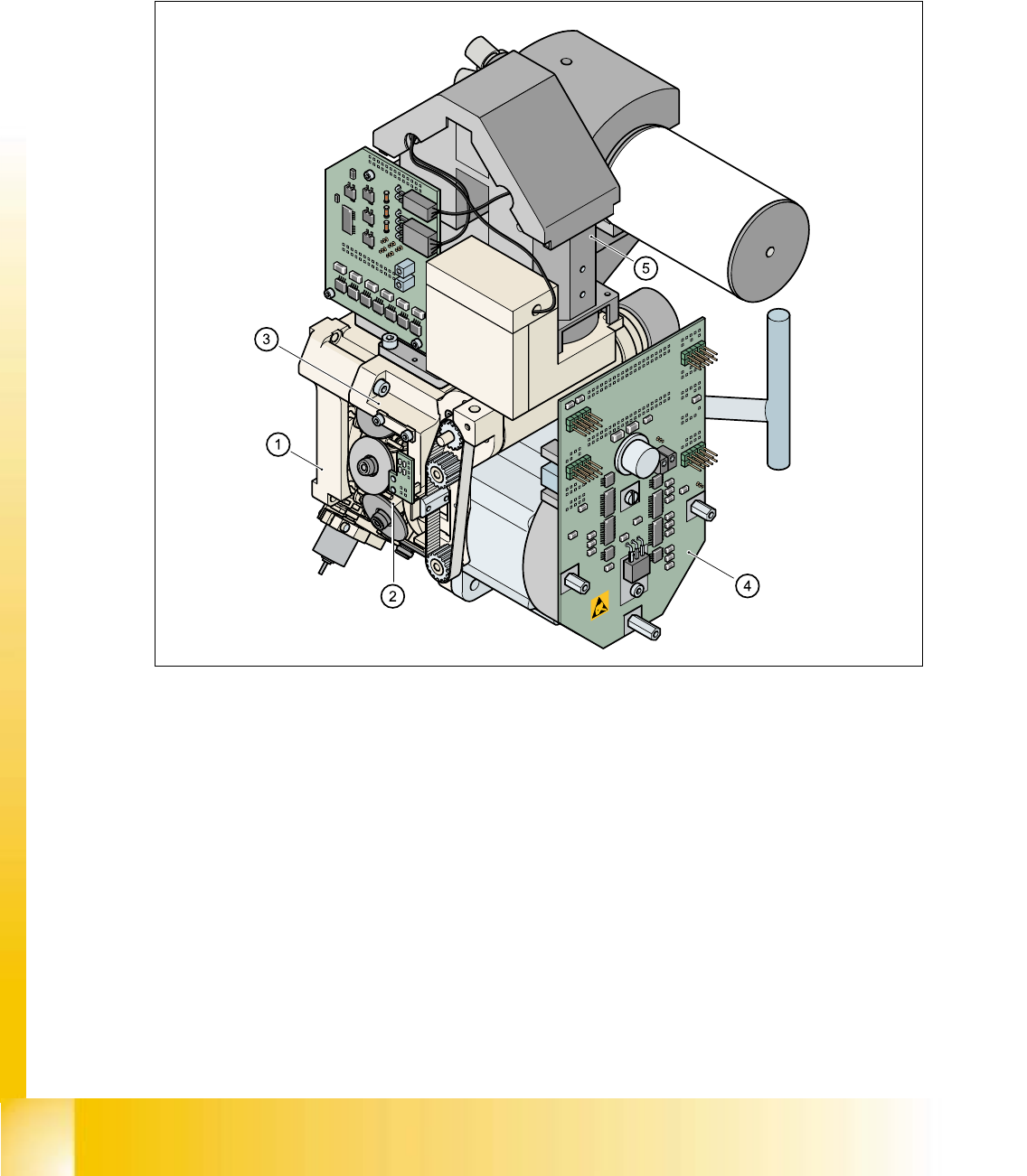
2.13 DLM1 C&P Head Overview
The HS-50 automatic placement system has four 12-segment type DLM1 revolver heads
(item no. 00335700-01). 2
2
Fig. 2.13 - 1 12-segment DLM1 revolver head - overview
(1) Back part, complete / DLM1 (Item no. 00335986-xx)
(2) Star, fitted (Item no. 00341181-xx) with 12 sleeves
(3) Front part, complete / DLM1 (Item no. 00335981-xx)
(4) SP6_12 intermediate distribution board, digital (Item no. 00330648-xx)
(5) 24x24 component camera (Item no. 00320549-xx)
Option:
DCA camera 15,6 x 15,7mm (Item no. 00337450-01) 2
Component - sensor (Item no. 00118021-01) 2