HS50_advance_level 1_20200522_221201 (1).pdf - 第63页
Studen t Guide HS-50 A dvanced I 06/200 2 Edition 2 Overview 33 2.13.1 Step s when pickin g up and pla cin g compon ent s – A PC B moves into t he placem ent area of the P CB conv eyor . – The right-hand rev olver h ead …
06/2002 Edition Student Guide HS-50 Advanced I
2 Overview
32
2.13 DLM1 C&P Head Overview
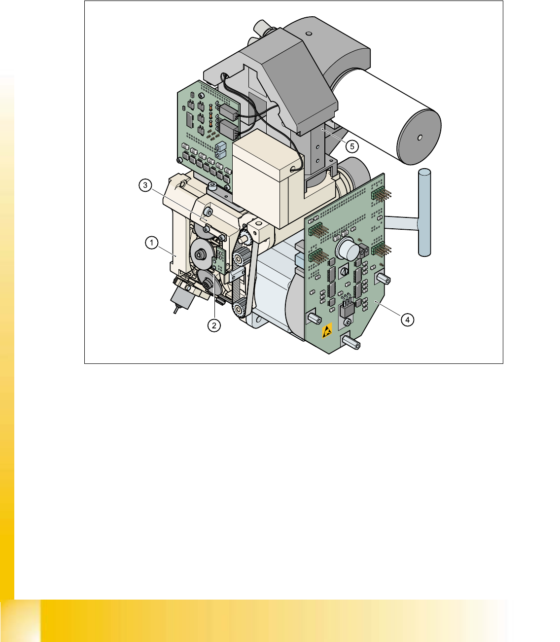
The HS-50 automatic placement system has four 12-segment type DLM1 revolver heads
(item no. 00335700-01). 2
2
Fig. 2.13 - 1 12-segment DLM1 revolver head - overview
(1) Back part, complete / DLM1 (Item no. 00335986-xx)
(2) Star, fitted (Item no. 00341181-xx) with 12 sleeves
(3) Front part, complete / DLM1 (Item no. 00335981-xx)
(4) SP6_12 intermediate distribution board, digital (Item no. 00330648-xx)
(5) 24x24 component camera (Item no. 00320549-xx)
Option:
DCA camera 15,6 x 15,7mm (Item no. 00337450-01) 2
Component - sensor (Item no. 00118021-01) 2

Student Guide HS-50 Advanced I 06/2002 Edition
2 Overview
33
2.13.1 Steps when picking up and placing components
– A PCB moves into the placement area of the PCB conveyor.
– The right-hand revolver head picks up components from the feeder modules.
– The left-hand revolver head waits for the fiducial measurement.
– Once the fiducial measurement is complete, the right-hand revolver head places components
while the left-hand revolver head picks up further components.
– The right-hand revolver head picks up components, and so on.
2.13.1.1 Position and function of the individual star stations (see Fig. 2.13 - 2)
Star station 1 2
Pick-up cycle 2
The nozzle is lowered onto the component. Once the valve positioning unit has opened the vac-
uum circuit to the nozzle, the nozzle draws up the component and removes it from the feeder mod-
ule. 2
Placement cycle 2
The valve positioning unit closes the vacuum channel to the nozzle. The nozzle, together with the
component, is lowered onto the PCB that has been moved into place. A short burst of compressed
air detaches the component from the nozzle and places it on the PCB. 2
Star station 3 2
Reject cycle
The valve positioning unit closes the vacuum channel to the nozzle. Defective components are
detached from the nozzle with a short burst of compressed air and are discarded. 2
Star station 7 2
The component is optically centered. 2
Star station 9 2
Pick-up cycle 2
The nozzle is rotated to the pick-up position. 2
Placement cycle 2
The placement angle of the component is corrected or the correct placement angle of the compo-
nent is set. 2
Between star station 11 and 12 2
Check the present and / or height from the component on the nozzle.
06/2002 Edition Student Guide HS-50 Advanced I
2 Overview
34
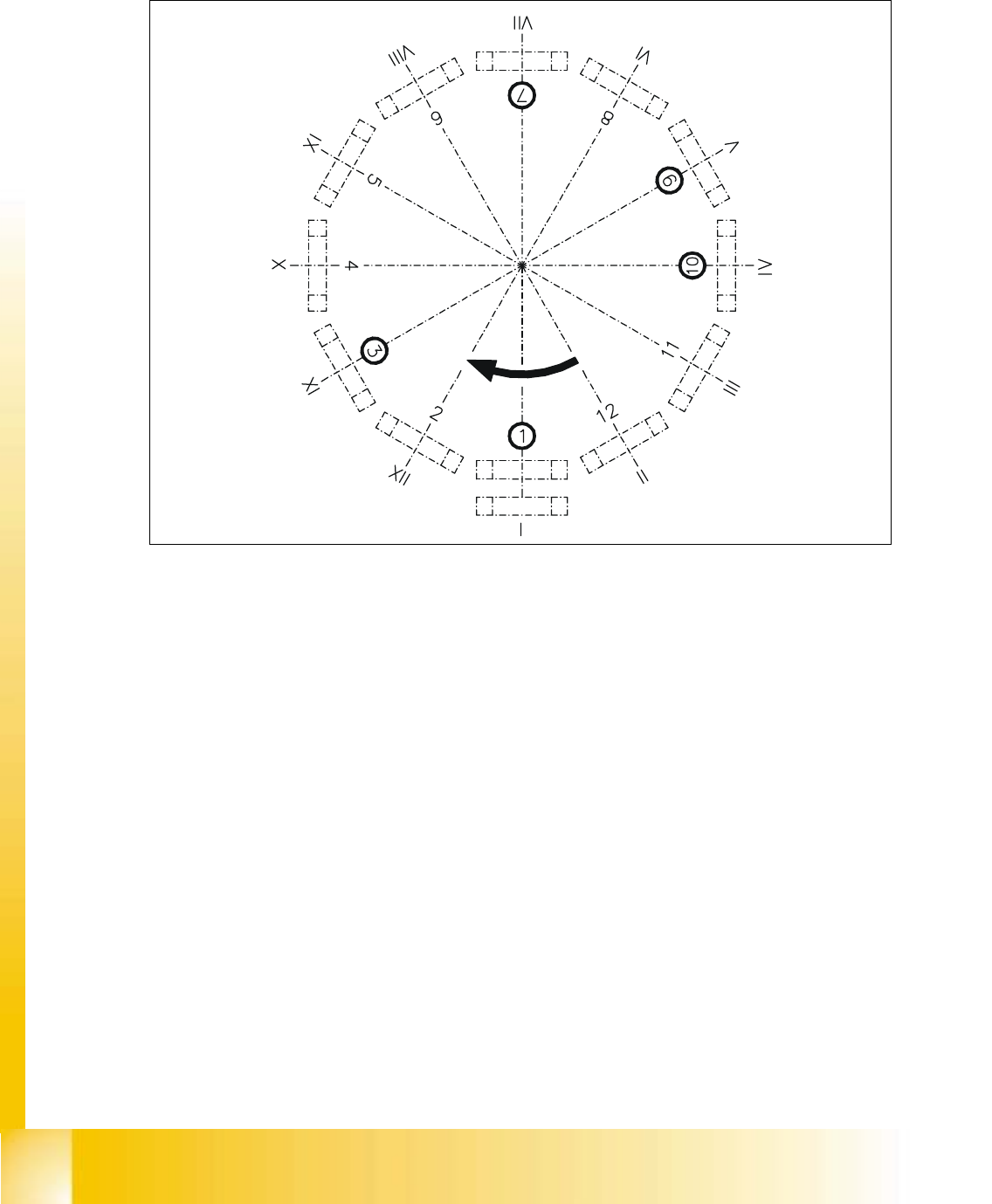
2.13.2 Overview of the functions of star stations 1 - 12
2
Fig. 2.13 - 2 Overview of the functions of star stations 1 - 12
Star station 1: pick up or place component 2
Star station 2: no function 2
Star station 3: discard component 2
Star station 4, 5 and 6: no function 2
Star station 7: optically center component 2
Star station 8: no function 2
Star station 9: rotate component 2
Star station 10: position for removing and inserting sleeves 2
Star stations 11 and 12: no function (optionally Component sensor) 2
I-XII Segment numbering 2