HS50_advance_level 1_20200522_221201 (1).pdf - 第79页
4 Com munication
06/2002 Edition Student Guide HS-50 Advanced I
3 Machine Reference Run
10
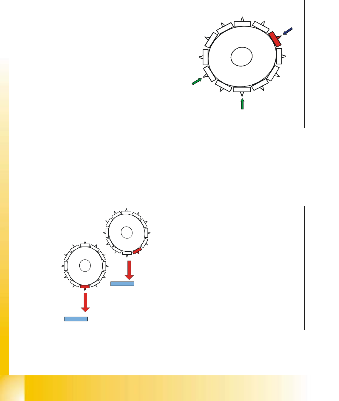
3.11 Vacuum check and all nozzle turned to 0°
Fig. 3.11 - 1 Vacuum check and all nozzle turned to 0°
3.12 Hight reference run
Fig. 3.12 - 1 Hight reference run
Ø
First of all the revolver head is moved to the
reject position by the gantry axes.
Ø
Whilst the star axis is indexing during the first
head cycle the DP station is swiveled in and
turns each segment to 0° position, figure 1.
Ø
Parallel to turning all nozzle the vacuum check is
operated.
Ø
The air kiss valve is opened and at the same time
the valve drive for the reject position is activated
and switches between open and closed. Anything
on the nozzle is rejected.
Ø
During the second head cycle the vacuum values
at the Pick up / Placement station are measured.
Ø
These are the reference values for each segment
for the vacuum checks during placement.
2
3
4
5
6
7
8
9
1
0
1
1
12
1
2.
3.
1.
2
3
4
5
6
7
8
9
10
1
1
1
2
1
2
3
4
5
6
7
8
9
1
0
1
1
12
1
Ø
Finall
y
the
g
antr
y
moves the placement heads above
the fixed transport rail.
Ø
The Z-axis runs down, and all segments touch the
transport rail.
Ø
The correct fitting on the sleeve and the nozzle type
is tested.
Ø
nozzle 1 defines the reference length.
Ø
All segments are measured according to there
specific length.
Ø
Exception: special nozzle with type number X9X
Ø
The maximum length tolerance is 0,4 mm:
If the length difference is too high an error message
is displayed.
Ø
The nozzle length is taken to calculate the placement
height for the following placements.
Ø
The gantries of one placement area work only for
this measurement sequentially.

4 Communication