00900170-01_ID_OIS_SIS_16.0_R18-2_EN_DE - 第56页
ASM OIS/SIS Datab ases 16.0 (R18 -2) / Interf ace Description 11/2018 Edition 56 Table 7-1 : Sta te machine with storage variables M : Save state C : Clear state R : Read the state with the highest priority number I : Ig…

ASM OIS/SIS Databases 16.0 (R18-2) / Interface Description 11/2018 Edition
55
7 OIS State Machines
7.1 Machines with One Processing Area
ASM OIS displays to the operator in which state the placement machine has been and for how
long. ASM OIS actually collects and records the events of the placement machine. The manner in
which the states are calculated from these events is shown at the end of this section. Each event is
assigned a timestamp from the station.
Explanation of terms
An action can set and/or clear one or more storage variables. An event has a unique name by
which it is identified. An event can be assigned an action which is always executed when this event
occurs. A state has a unique name. An action can be assigned to a state. This action is then
always executed when this state is entered. A storage variable exists for each state. Each storage
variable can be set or cleared. A state transition describes how the machine behaves when it
receives an event. A state transition can contain two different entries:
● The new state is specified directly.
● The new state is determined by reading the storage variable. If several storage variables are
set, the state with the highest priority is determined.
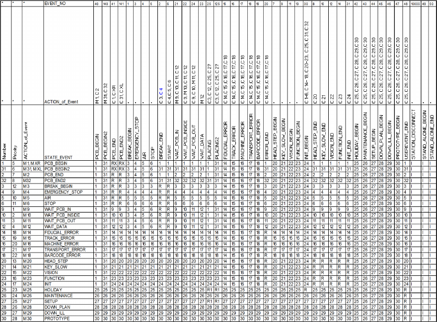
The following table describes a state machine with storage variables. The time a machine spends
in a particular state is assigned to that state.
Example
The machine is in state 10 OIS_WAIT_PCB_INSIDE (waiting for a PCB in the center conveyor).
Event 15 FIDUCIAL_ERROR now occurs. First, the action for the FIDUCIAL_ERROR event is
executed, "c14, c16, c17, c18". Secondly, the state transition is performed, i.e. the machine
switches to state 14 OIS_FIDUCIAL_ERROR. Thirdly, the action for the OIS_FIDUCIAL_ERROR
state is executed, "m 14".
NOTICE
Events 125, 140 and 141 in the downstream state automaton are artificially generated
events for conveyor track 2. This means, for example, that if the machine sends event 25
from conveyor track 2, it must be input to the state automaton as event 125. There is no
change for events on conveyor track 1.
ASM OIS/SIS Databases 16.0 (R18-2) / Interface Description 11/2018 Edition
56
Table 7-1: State machine with storage variables
M:
Save state
C:
Clear state
R:
Read the state with the highest priority number
I:
Ignore
R1:
For machines with one placement area: read the state like R.
For machines with 2 placement areas: the state transition is executed for both placement areas.
RX:
For machines with 2 placement areas: the state transition is executed for both placement areas R.
Placement process on 2 transport conveyors: The state changes to PCB_BEGIN or PCB_BEGIN2.
XR/XL:
Status that indicates whether the placement process is on the right (XR) or left (XL) transport
conveyor.
ASM OIS/SIS Databases 16.0 (R18-2) / Interface Description 11/2018 Edition
57
7.2 Machines with Two Processing Areas
For example: SIPLACE SX4, X4, X4 S, X4i, X4i S, X3, X3 S, D4, D3, HS-50, HS-60, HF
There is a separate state machine for machines with two processing areas.
NOTICE
If an X4 machine spends one minute placing a PCB in processing area 1 and then
spends another minute placing a PCB in processing area 2, the machine should show
50% of its time in placement state and 50% in waiting state if a PCB is inserted into the
machine every two minutes.
On this basis, it is necessary to map an X4 machine to at least two state machines. In other words,
one state machine for each processing area. The machine for a processing area is therefore the
same as the machine for an X2, for example. This means that the states of processing areas 1 and
2 each account for half of the state of the X4 machine.
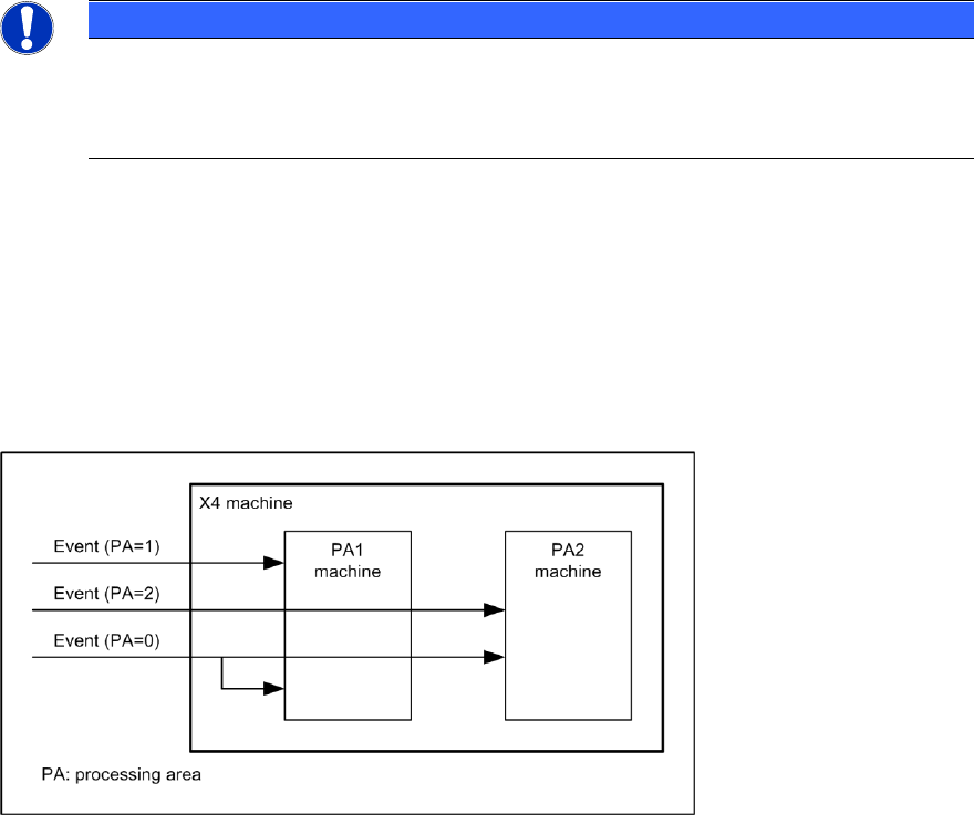
When an event occurs on the X4 machine, this event is only forwarded to the appropriate machine
for the processing area, depending on the assignment of event to processing area. If an event is
not assigned to any processing area, it is forwarded to both processing area machines. See also
the following diagram.
Figure 7-1: X4 state machine
7.3 I-Placement
For SIPLACE X4i machines with station software version 7xx, the "I-Placement" option is
supported.
In previous OIS state machines for SIPLACE Placement machines, it was only possible to create
states for one processing area at a time; even with dual-lane transport, only one PCB was
produced at any one time.
Starting with this version, the "I-Placement" option can process 2 PCBs simultaneously in one
processing area. This functionality has caused changes to the OIS state machine.
Previous station types are also supported by the new OIS state machine.