00900170-01_ID_OIS_SIS_16.0_R18-2_EN_DE - 第58页
ASM OIS/SIS Datab ases 16.0 (R18 -2) / Interf ace Description 11/2018 Edition 58 7.4 Synch ronous Dual Conv eyo r Station software vers ions 605.xx and 7 xx pro vide enhanced data quality for operat ion with synchronous …
ASM OIS/SIS Databases 16.0 (R18-2) / Interface Description 11/2018 Edition
57
7.2 Machines with Two Processing Areas
For example: SIPLACE SX4, X4, X4 S, X4i, X4i S, X3, X3 S, D4, D3, HS-50, HS-60, HF
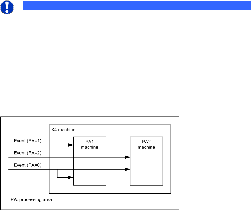
There is a separate state machine for machines with two processing areas.
NOTICE
If an X4 machine spends one minute placing a PCB in processing area 1 and then
spends another minute placing a PCB in processing area 2, the machine should show
50% of its time in placement state and 50% in waiting state if a PCB is inserted into the
machine every two minutes.
On this basis, it is necessary to map an X4 machine to at least two state machines. In other words,
one state machine for each processing area. The machine for a processing area is therefore the
same as the machine for an X2, for example. This means that the states of processing areas 1 and
2 each account for half of the state of the X4 machine.
When an event occurs on the X4 machine, this event is only forwarded to the appropriate machine
for the processing area, depending on the assignment of event to processing area. If an event is
not assigned to any processing area, it is forwarded to both processing area machines. See also
the following diagram.
Figure 7-1: X4 state machine
7.3 I-Placement
For SIPLACE X4i machines with station software version 7xx, the "I-Placement" option is
supported.
In previous OIS state machines for SIPLACE Placement machines, it was only possible to create
states for one processing area at a time; even with dual-lane transport, only one PCB was
produced at any one time.
Starting with this version, the "I-Placement" option can process 2 PCBs simultaneously in one
processing area. This functionality has caused changes to the OIS state machine.
Previous station types are also supported by the new OIS state machine.

ASM OIS/SIS Databases 16.0 (R18-2) / Interface Description 11/2018 Edition
58
7.4 Synchronous Dual Conveyor
Station software versions 605.xx and 7xx provide enhanced data quality for operation with
synchronous dual conveyor.
This chapter describes the operating data written in the OIS database during production with
synchronous dual conveyor in station software 605.xx and 7xx.
NOTICE
Previous station software versions do not provide the described data quality.
7.4.1 Station Software 605.xx
PCB
The attribute lBoardNumber is increased in step size of 4 for both transport conveyors.
Until now, the attribute was increased in step size 2.
For synchronous dual conveyor, two boards are written in the OIS database.
Example
3 boards are produced without synchronous dual conveyor on the right transport conveyor.
After that, 6 boards are produced with synchronous dual conveyor.
Then, the following board numbers exist in the OIS database:
1, 5, 9, 13, 13, 17, 17, 21, 21.
The boards with lBoardNumber 13, 17, 21 exists once for ucConveyor = 1 and once for
ucConveyor = 2.
Cycle time sDuration and end date/time dtTime are identical for synchronous dual conveyor.
Component consumption
The component consumption is sent in sum for every board.
For the example described above, the following consumption data is available for the following
board numbers: 1, 5, 9, 13, 17, 21.
Events
The PCB_BEGIN, PCB_END and PLACING events are sent only once for synchronous dual
conveyor.
For the example described above, PCB_BEGIN is only available for the following board numbers:
1, 5, 9, 13, 17, 21.
ASM OIS/SIS Databases 16.0 (R18-2) / Interface Description 11/2018 Edition
59
7.4.2 Station Software 7xx
The 7xx station software handles synchronous dual conveyor differently than the 605.xx software
does. This station software handles each board individually. This means that each board gets its
own board ID (IBoardNumber) and the events PCB-BEGIN and PCB_END are sent for each board.
OIS generates a database entry for each board in the BOARD table and an event entry for each
event in the EVENT table in the OIS database.
7.5 MTC / WPC Track
In previous station software versions, the MTC / WPC was located on track 0 (sTrack) in the OIS
database. In the SIS database these components were located on track 1 (sTrack). This caused a
difference between the OIS station view and the SIS line view.
As of the station software versions 605 and 701 the MTC / WPC is located on track 1 in both
databases.
NOTICE
The V_USEDCOMPONENTS6 view (see section 5.11.1) shows track 0 (sTrack) as
track 1.
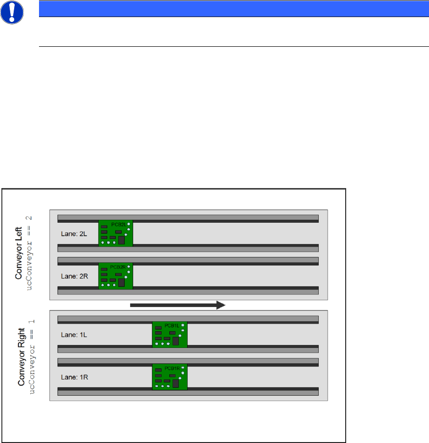
7.6 Quad Lane Support
The station software as of 702 supports the "Quad Lane" conveyor mode. This mode means that a
placement machine is equipped with two lanes per conveyor, i.e. each conveyor has two sub-
lanes. Each sub-lane can handle a PCB autonomously but not independently. The meaning of “not
independently” is, that the two lanes of a conveyor always run in synchronous mode, i.e. PCBs on
both lanes enter and leave a certain processing area at the same time.
Figure 7-2: Quad Lane