00900170-01_ID_OIS_SIS_16.0_R18-2_EN_DE - 第60页
ASM OIS/SIS Datab ases 16.0 (R18 -2) / Interf ace Description 11/2018 Edition 60 The sub-lane inform ation can be f ound in the lSubConvey or column in the BO ARD table of the OIS database. If the station does no t run i…
ASM OIS/SIS Databases 16.0 (R18-2) / Interface Description 11/2018 Edition
59
7.4.2 Station Software 7xx
The 7xx station software handles synchronous dual conveyor differently than the 605.xx software
does. This station software handles each board individually. This means that each board gets its
own board ID (IBoardNumber) and the events PCB-BEGIN and PCB_END are sent for each board.
OIS generates a database entry for each board in the BOARD table and an event entry for each
event in the EVENT table in the OIS database.
7.5 MTC / WPC Track
In previous station software versions, the MTC / WPC was located on track 0 (sTrack) in the OIS
database. In the SIS database these components were located on track 1 (sTrack). This caused a
difference between the OIS station view and the SIS line view.
As of the station software versions 605 and 701 the MTC / WPC is located on track 1 in both
databases.
NOTICE
The V_USEDCOMPONENTS6 view (see section 5.11.1) shows track 0 (sTrack) as
track 1.
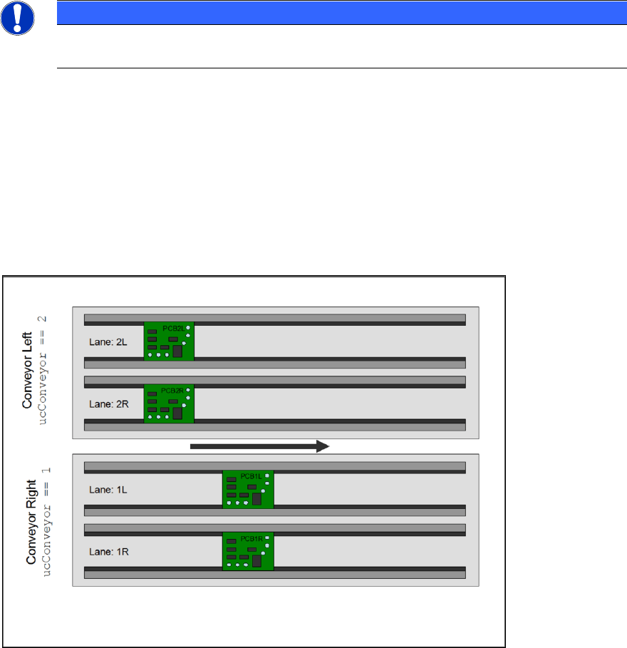
7.6 Quad Lane Support
The station software as of 702 supports the "Quad Lane" conveyor mode. This mode means that a
placement machine is equipped with two lanes per conveyor, i.e. each conveyor has two sub-
lanes. Each sub-lane can handle a PCB autonomously but not independently. The meaning of “not
independently” is, that the two lanes of a conveyor always run in synchronous mode, i.e. PCBs on
both lanes enter and leave a certain processing area at the same time.
Figure 7-2: Quad Lane
ASM OIS/SIS Databases 16.0 (R18-2) / Interface Description 11/2018 Edition
60
The sub-lane information can be found in the lSubConveyor column in the BOARD table of the OIS
database.
If the station does not run in "Quad Lane" conveyor mode, this entry contains the value "0". In case
of "Quad Lane" conveyor mode, this entry is either "1" for the right lane or "2" for the left lane.
Applied to the example shown in the figure above, this would result in the following table entries.
strBoard
ucConveyor
lSubConveyor
lBoardNumber
PCB2L
2
2
20
PCB2R
2
1
21
PCB1L
1
2
22
PCB1R
1
1
23
NOTICE
Please note that each PCB gets its own lBoardNumber. The values shown in the
lBoardNumber column are just examples and do not mean that the PCB on the left lane
on the left conveyor always gets the lowest number in "Quad Lane" conveyor mode. It
just means that each PCB gets a unique lBoardNumber.
This behavior is the same for synchronous and asynchronous mode.
The OIS server adds the following board specific database entries while a board gets produced.
EVENT table
● New Event: PCB_BEGIN when the production is started.
● New Event: PCB_END when the production is completed.
BOARD table
● A new row is added to the BOARD table describing the PCB.
USEDCOMPONENTS table
● A new row is added to the USEDCOMPONENT table for each component that has been
placed.
In "Quad Lane" conveyor mode these entries are written for each of the quad boards which can be
produced at a specific time.
ASM OIS/SIS Databases 16.0 (R18-2) / Interface Description 11/2018 Edition
61
8 Appendix
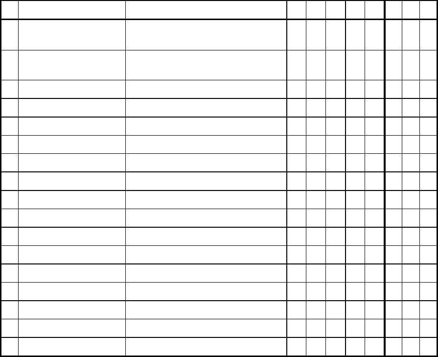
8.1 Time Slices
The configuration of time slices is described below. A time slice is a combination of states of a
placement machine. A state can be assigned to a time slice from 0% to 100%. The time slice can
be freely defined by the customer.
The following setting (table) is supplied as the ASM standard. This table corresponds to the
assignment of states to time slices (shares of time) in MaDaMaS.
MaDaMaS shares of time:
T
1
= running
T
2
= waiting
T
3
= blocked
T
4
= interrupted
T
5
= fault
T
6
– T
8
= not used
Available time slices:
T
a
= technical availability, manufacturer responsibility
T
b
= allocation time (on-period
Displayed state:
T
9
= state display in the "States" view table
0 = not displayed
1 = displayed
No.
State
Description
T
1
T
2
T
3
T
4
T
5
T
a
T
b
T
9
1
OIS_PCB_BEGIN ||
OIS_PCB_BEGIN2
Start PCB production
100
0
0
0
0
100
100
0
2
OIS_PCB_END ||
OIS_PCB_END2
End PCB production
0
100
0
0
0
100
100
0
3
OIS_BREAK_BEGIN
Abort, production interrupted
0
0
0
100
0
100
100
0
4
OIS_EMERGENCY_STOP
EMERGENCY STOP button was pressed
0
0
0
100
0
100
100
1
5
OIS_AIR
Compressed air supply malfunction
0
0
0
0
100
100
100
1
6
OIS_STOP
Stop button was pressed
0
0
0
100
0
100
100
0
9
OIS_WAIT_PCB_IN
Waiting for PCB in input conveyor
0
100
0
0
0
100
100
0
10
OIS_WAIT_PCB_INSIDE
Waiting for PCB in center conveyor
100
0
0
0
0
100
100
0
11
OIS_WAIT_PCB_OUT
Waiting for output conveyor to become free
0
0
100
0
0
100
100
0
12
OIS_WAIT_DATA
Waiting until data has been sent
0
100
0
0
0
100
100
0
14
OIS_FIDUCIAL_ERROR
A fiducial was not recognized
0
0
0
0
100
100
100
0
15
OIS_TRACK_ERROR
Track empty
0
0
0
0
100
100
100
0
16
OIS_MACHINE_ERROR
Fatal machine error has occurred
0
0
0
0
100
0
100
1
17
OIS_TRANSPORT_ERROR
Fatal transport error has occurred
0
0
0
0
100
100
100
0
18
OIS_BARCODE_ERROR
Fatal barcode error has occurred
0
0
0
0
100
100
100
0
20
OIS_HEAD_STEP
Cycle mode active
0
0
0
100
0
100
100
1
21
OIS_KEY_SLOW
Key switch on slow
0
0
0
100
0
100
100
1