3. SM471_Introduction(Kor_Ver1).pdf - 第60页
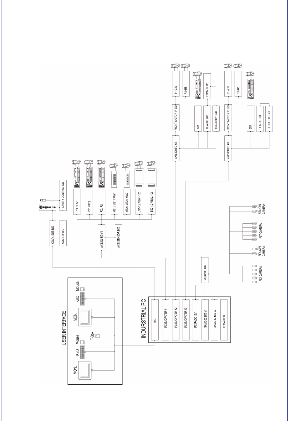
3-4 Samsung Component Pla cer SM471 Introduction 3.2.2. 제어부 구성 그림 3.3 제어부 구성도
3-3
장비의
명칭
및
구성
3.2. 시스템 구성
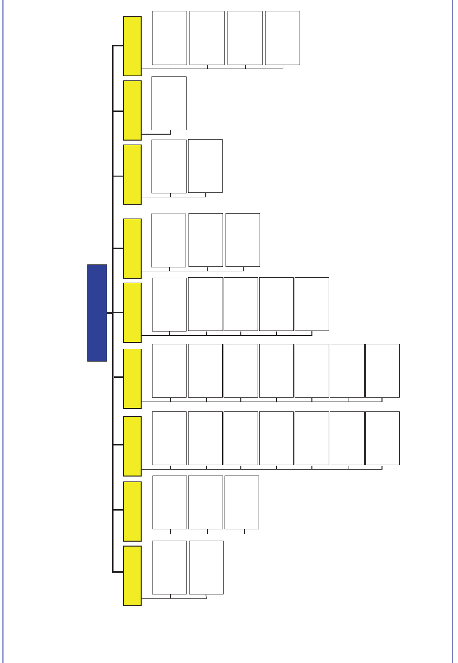
3.2.1. 기구부 구성
그림
3.2
기구부
구성도
zt[^XGὤẠ⺴GẠ㉥
zt[^XGὤẠ⺴GẠ㉥
Main Frame XY Gantry Head1 Cover
Feeder Base ANC
Conveyor&BUT
Base Frame
Electrical Unit
. Control Part
. Drive Part
Z Axis (20Axis)
. Motor
. Spline
Theta Axis
(10 Axis)
. Motor
Theta Axis
(10 Axis)
. Motor
Z Axis (20 Axis)
. Motor
. Spline
S Axis (2 Axis)
. Motor
S Axis (2 Axis)
. Motor
Flying Camera
.
FOV 24mm
. FOV 24mm Mega
Pixel Cam. (Option)
Flying Camera
.
FOV 24mm
. FOV 24mm Mega
Pixel Cam. (Option)
Nozzle
Pneumatic
Fiducial
Camera
Head2
Nozzle
Fiducial
Camera
X-Gantry1
. Motor/Encoder
. Frame
X-Gantry2
. Motor/Encoder
. Frame
Y Axis
. Motor/Encoder
. Frame
Work Station
.Width Control
Entry Shuttle
Exit Shuttle
Electrical
Module
Backup Table
Extemal
Cover
Operation
Panel
Acrylic
Window
Front
Rear
Docking Cart
Feeder Base
(Option)
Front
Rear
Pneumatic
System
Mist Seperate
Pressure
Gauge
Regulater
Manifold
Pneumatic
3-4
Samsung Component Placer SM471 Introduction
3.2.2. 제어부 구성
그림
3.3
제어부
구성도
3-5
장비의
명칭
및
구성
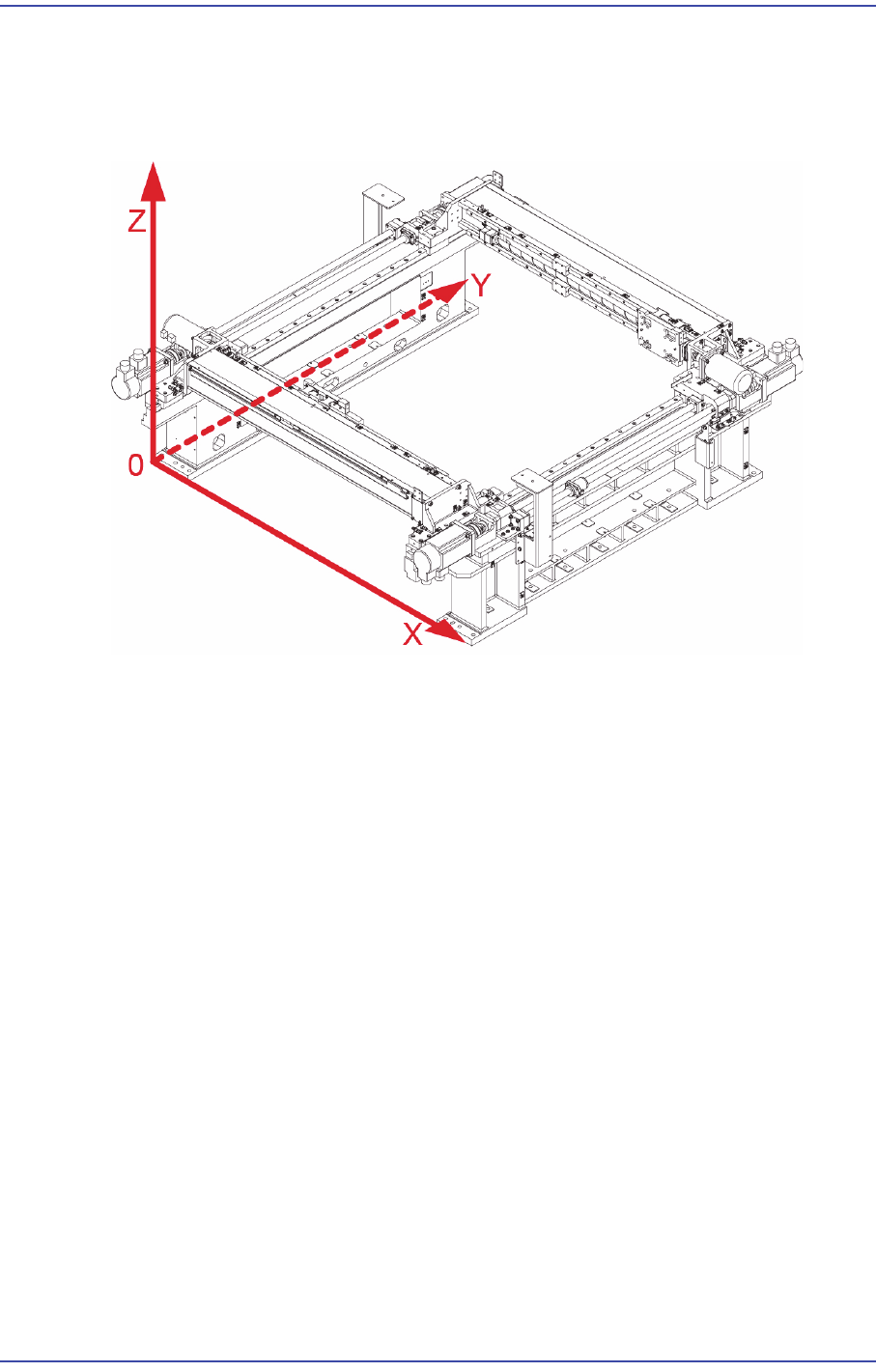
3.3. 좌표계
본 장비의 기본적인 좌표계는 다음의 그림에 나타낸 바와 같습니다.
그림
3.4
장비의
좌표계
3.3.1. X, Y축
Head, ANC, 장착점(Placement Position), 기판 Fiducial Mark의 위치를 표시합니다.
3.3.2. Z 축
Z축은 Head에서 노즐 끝의 위치를 표시하며 고정된 기판의 상면의 위치를 0으로 표
시합니다.