3OM-1751-002w_G5S.pdf - 第104页
3OM-1751 1-50 1303-001 • Component Recognition Camera Offset T eaching Jig For the component recognition camera of fset teaching, the following jig is used. Before the teaching operation, place the jig at its setup posit…
3OM-1751
1-491303-001
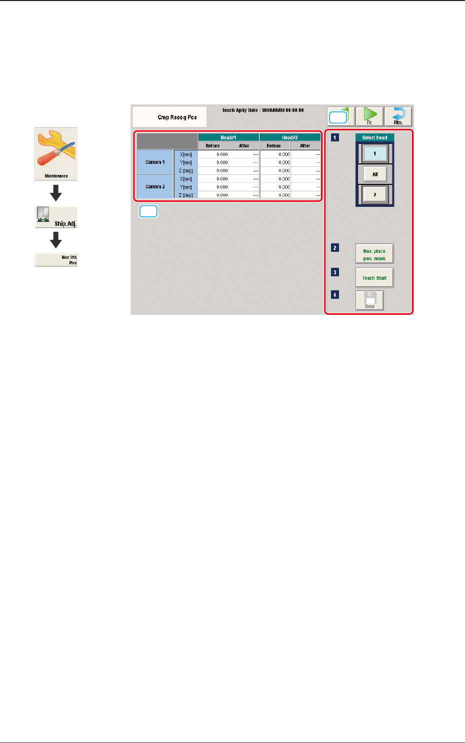
5.9 "Cmp Recog Pos" Window
This window enables you to perform a teaching operation on the component
recognition camera offsets (X (mm) Horizontal, Y (mm) Vertical, and Z (deg)
Theta).
[1]
[2]
F3A36
[1] Teaching Data Display Section
Displayed are the each offset data items for the designated camera and head.
[2] Teaching Procedure Display Area
Displayed are the buttons to be used for the teaching operations.
Select head
In this section, the buttons showing the component recognition cameras
corresponding to each head are displayed as images.
Select the component recognition camera for which the teaching is
performed.
[Noz. Place. Pos. move] Button
Using this button, the head is moved to the position where the nozzle to be
used for the teaching can be attached easily.
[Teach Start] button
When pressed, this button executes the teaching operation.
[Save] button
When this button is pressed, the teaching results are saved.
Graphic
Development
5.9 "Cmp Recog Pos" Window
3OM-1751
1-501303-001
•
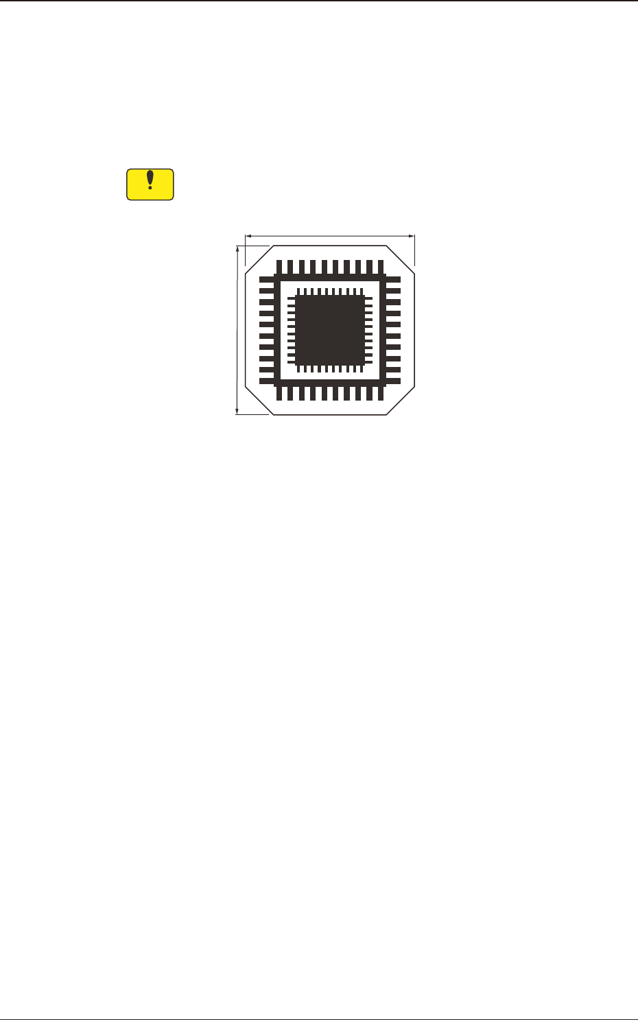
Component Recognition Camera Offset Teaching Jig
For the component recognition camera offset teaching, the following jig is used.
Before the teaching operation, place the jig at its setup position and when the
teaching is completed, remove it.
QFP Glass Jig JG-0188 (KYB-M381P-00, Standard Equipment)
Notice
This jig is fragile, so take the greatest care to handle it.
12 mm
12 mm
On the glass, the two patterns for the positional calculation are vapor-deposited.
QFP Glass Jig JG-0188 F3A37
•
Jig Pick-up Nozzle
For the pick-up of the QFP glass jig, the jig nozzle (standard equipment) or the
normal vacuum nozzle HV19C is used.
Before the teaching operation, change the nozzle in the "NOZ.CHNG." window
(Operation Sequence: Select [Unit Adj.] button in the Menus for Maintenance
→
Select [Noz Chng.] button).
5.9 "Cmp Recog Pos" Window

3OM-1751
1-511303-001
•
Component Recognition Camera Offset Teaching Procedure
Procedure
(1) Before the teaching operation, place the QFP glass jig at its setup position
with the vapor-deposited surface turned down.
(2) Press the [Noz. Place. Pos. move] button
(Move the head to the position where the nozzle to be used for teaching can
be attached easily.)
(3) Press the [Teach Start] button.
(The component recognition camera offset (X (Horizontal), Y (Vertical) and
Z (Angle)) teaching will be executed.)
•
The beam selected in the position setting operation is move to the jig setup
position and the glass jig is recognized using the PEC recognition camera.
After that, the jig in the jig setup position is picked up and moved to the
position above the component recognition camera. The nozzle is lowered
to the focus point of the jig and the recognition is performed. Then, the
camera offset is calculated.
•
When the teaching is started, the start conditions are checked.
•
When any recognition error occurs during the teaching operation or the
[STOP] button is pressed on the operation penal, the machine is stopped
temporarily. In this case, re-start is available.
•
During this temporary stop mode, the selection of any other menu item is
unavailable.
When the offset teaching is completed, the jig is returned to the specied
jib setup position and the designated head returns to the home position
automatically.
The teaching results and mark recognition results during the teaching (XY
Angles) are displayed in the "X (Horizontal) (mm)", "Y (Vertical) (mm)",
and "Angle Z (
°
)" data boxes in the "PEC Recognition Camera & Beam
Offset" window.
(4) Press the [Save] button.
(When this button is pressed, the teaching results are saved.)
5.9 "Cmp Recog Pos" Window