3OM-1751-002w_G5S.pdf - 第112页
3OM-1751 1-58 1303-001 5.12 "Fly Recog Camr" Window The set parameters are used to prevent a component from getting affected by the delay and staying out of camera eld of view. [1] [2] F3A43 [1] T eaching Data…
3OM-1751
1-571303-001
•
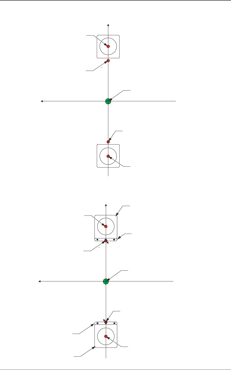
Head Rotational Center Offset
Xm-Ym: Machine Reference Coordinate System
Xm(+)
Ym(+)
Head Rotational Center
PEC Recognition Camera Center
Pm. Machine Reference Coordinate Origin
PEC Recognition Camera Center
Head Rotational Center
F3A41
•
Reference Mark Offset
Xm-Ym: Machine Reference Coordinate System
Xm(+)
Ym(+)
Component Recognition Camera
Head Rotational Center
Reference Mark
PEC Recognition Camera Center
Pm. Machine Reference Coordinate Origin
Reference Mark
PEC Recognition Camera Center
Component Recognition Camera
Head Rotational Center
F3A42
5.11 "Head Cntr Mark Pos" Window
3OM-1751
1-581303-001
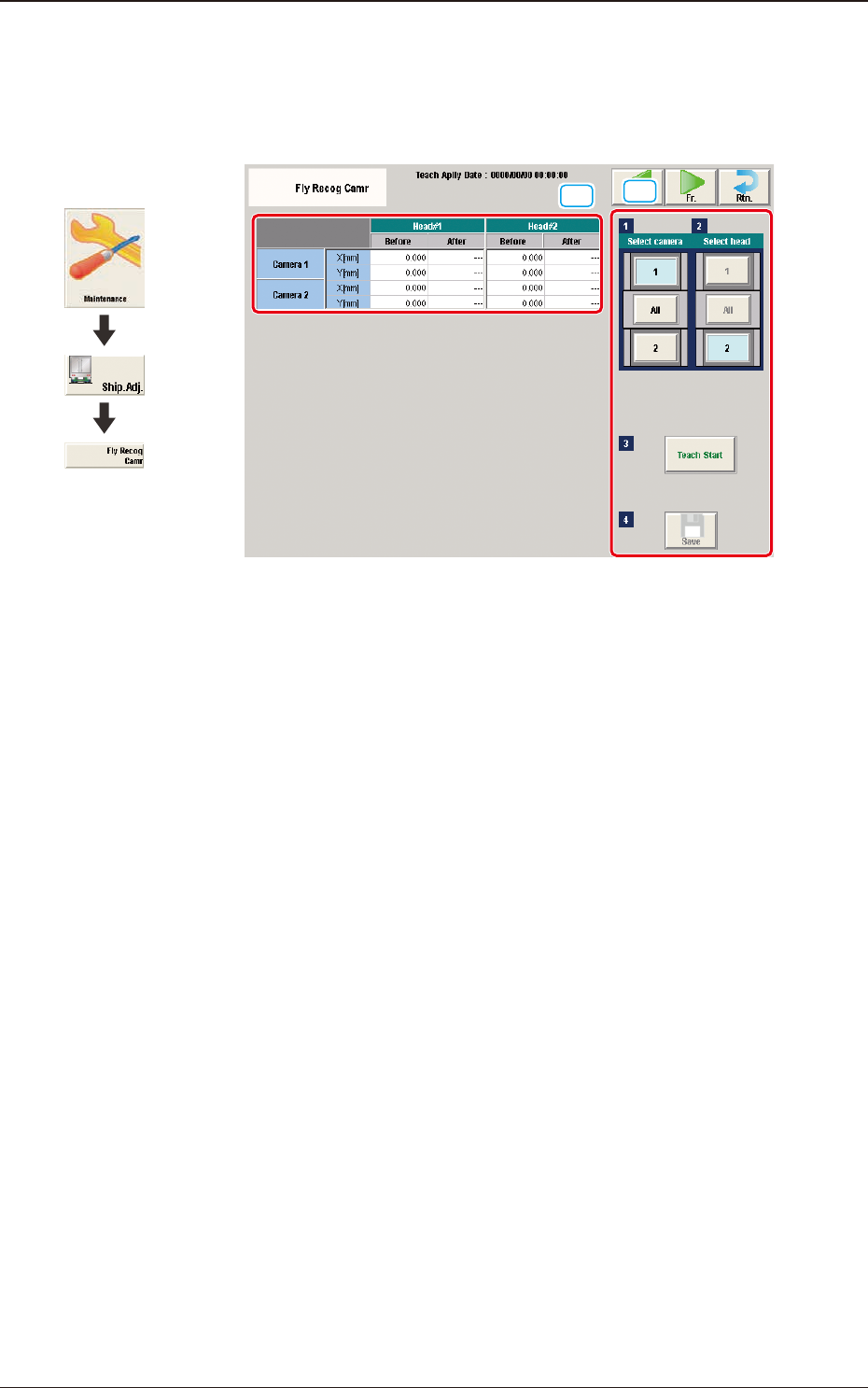
5.12 "Fly Recog Camr" Window
The set parameters are used to prevent a component from getting affected by the
delay and staying out of camera eld of view.
[1]
[2]
F3A43
[1] Teaching Data Display Section
Displayed are the offset data items for the designated camera.
[2] Teaching Procedure Display Area
Displayed are the buttons to be used for the teaching operations.
Select camera
Each component recognition camera in the graphic image of the machine is
provided with a button function. When a button is pressed, the corresponding
component recognition camera is selected as an object one for the teaching
operation.
Select head
Each head in the graphic image of the machine is provided with a button
function.
When a button is pressed, the corresponding head is selected as an object
head for the teaching operation.
The teaching is performed in accordance with the selected and displayed
window.
[Teach Start] button
When pressed, this button executes the teaching operation.
[Save] button
When this button is pressed, the teaching results are saved.
Graphic
Development
5.12 "Fly Recog Camr" Window

3OM-1751
1-591303-001
•
Teaching Procedure
Procedure
(1) Select the Camera and Head (1, 2 or All) for which the teaching is performed.
(2) Press the [Teach Start] button.
(Move the PEC recognition mark onto the reference mark on the side of the
component recognition camera lighting and recognize the reference mark
while the camera is in the stop mode. (At that time, the beam position is
regarded as (X, Y).)
Fix the beam X onto the coordinate X and move the beam Y at the constant
speed (2m/s). Then, when the PEC recognition camera passes over the
reference mark, perform the y image shooting to recognize the mark.
The difference from the data obtained when the camera is stopped, is
regarded as the y recognition offset.
•
When the teaching is started, the start conditions are checked.
•
During this temporary stop mode, the selection of any other menu item is
unavailable.
When the offset teaching is completed, the designated head returns to the
home position automatically.
The teaching results are displayed in the "Fly Recog Camr Offset
Teaching" Display Area.
(3) Press the [Save] button.
(When this button is pressed, the teaching results are saved.)
5.12 "Fly Recog Camr" Window