3OM-1751-002w_G5S.pdf - 第120页
3OM-1751 1-66 1303-001 • Nozzle Position T eaching Procedure Procedure (1) Select the head and nozzle (from Head 1 or 2 and Nozzle 1 to 15) for which the nozzle level offset teaching is performed. (2) Press the [T each S…

3OM-1751
1-651303-001
Change window display
Pressing each button corresponding to each teaching operation, changes over
the window to the corresponding teaching window.
When the window is changed over, the teaching in the displayed window is
performed.
The buttons corresponding to each window are as follows.
Noz. Lv.
: The window is changed to the teaching window for the nozzle
level.
Noz. Pos.
: The window is changed to the teaching window for the
reference nozzle position.
[Teach Start] button
When pressed, this button executes the teaching operation.
[Save] button
When this button is pressed, the teaching results are saved.
•
Nozzle Level Teaching Procedure
Procedure
(1) Select the head (1, 2 or All) for which the nozzle level offset teaching is
performed.
(2) Press the [Teach Start] button.
(When nozzle level will be measured using the line sensor and the read data
will be used as offset data.)
•
When the teaching is started, the start conditions are checked.
•
The teaching results are displayed in the "After" section in the "Noz Lv.
Offset" Display Area.
When the teaching is completed, the designated head is returned to the home
position automatically.
(3) Press the [Save] button.
(When this button is pressed, the teaching results are saved.)
5.15 "Noz Lv./Pos." Window

3OM-1751
1-661303-001
•
Nozzle Position Teaching Procedure
Procedure
(1) Select the head and nozzle (from Head 1 or 2 and Nozzle 1 to 15) for which
the nozzle level offset teaching is performed.
(2) Press the [Teach Start] button.
(The designated head (No. 1 or 2) is moved to the specied position and the
nozzle position offset teaching is executed.)
•
When the teaching is started, the start conditions are checked.
•
The teaching results are displayed in the "After" section in the "Noz Pos
Offset" Display Area.
•
During this temporary stop mode, the selection of any other menu item is
unavailable.
When the teaching is completed, the designated head is returned to the home
position automatically.
(3) Press the [Save] button.
(When this button is pressed, the teaching results are saved.)
•
Error Condition
When a nozzle recognition error occurs during the nozzle position offset
teaching, the machine is not stopped, but the teaching is continued to the end.
The nozzle where an error occurred, is skipped.
The error existence can be conrmed in the "Recall" function.
5.15 "Noz Lv./Pos." Window
3OM-1751
1-671303-001
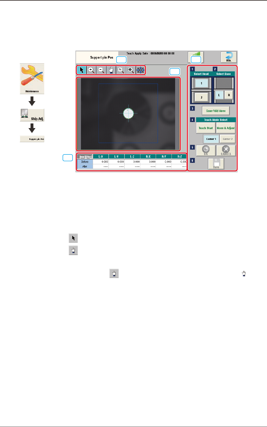
5.16 "Support pin Pos" Window
This window enables the operator to perform the teaching operation on the PCB
support pin position.
[2]
[1]
[3]
[4]
F3A47
[1] Display Area Operation Button
Using the following buttons, the mode is changed to enlarge or move the
image displayed in the recognition image display area [2].
[
] button
: Normal Operation Mode
[
] button
: Image Movement Mode
After changing to the image movement mode using the
[
] button (the shape of the pointer is changed to
mark), drag the image to be moved (pressing the left button
of the mouse, turn the ball to move the image).
Graphic
Development
5.16 "Support pin Pos" Window