3OM-1751-002w_G5S.pdf - 第124页
3OM-1751 1-70 1303-001 • T eaching Procedure Procedure (1) Select the head to be used for the teaching operation. (2) Select the base for which the teaching operation is performed. (3) Press the [Conv W id Move] button. …

3OM-1751
1-691303-001
[2] Recognition Image Display Section
The recognition result is displayed.
[3] Teaching Result
Before
: Displayed are the offset values before the teaching operation.
After
: Displayed are the offset values after the teaching operation.
[4] Operation buttons
Select Head
Each head in the graphic image is provided with a button function. Select the
head where the support pin position teaching is performed.
Select Base
Each base in the graphic image is provided with a button function. Select the
base where the support pin position teaching is performed.
[Conv Wid Move] Button
When this button is pressed, the head is evacuated and the conveyor width is
extended to the limit.
Tch Type Select
The teaching mode is selected in this area.
[Teach Start] Button :
When this button is pressed, the support pin
position teaching is performed automatically.
[Move & Adjust] Button :
When this button is pressed, the support pin's
rst and second positions are taught manually.
[OK] button
When this button is pressed, the teaching results are reected on the machine
operation.
[CANCEL] button
When this button is pressed, the teaching results are cancelled.
[Save] button
When this button is pressed, the teaching results are saved.
•
Teaching Jig
For the PCB support pin position teaching, the PCB support pin position
teaching jig is used.
5.16 "Support pin Pos" Window

3OM-1751
1-701303-001
•
Teaching Procedure
Procedure
(1) Select the head to be used for the teaching operation.
(2) Select the base for which the teaching operation is performed.
(3) Press the [Conv Wid Move] button.
(The conveyor will move to the setup position).
(4) Setup the PCB support pin teaching jig on the two locations; upper left and
lower right.
(5) Select the teaching mode and perform the teaching operation.
[Teach Start] Button
: When selected, go to step [7] and later.
[Move & Adjust] Button
: When selected, go to step [6] and later.
(6) Perform and manual alignment operation for each support pin in the manual
alignment window.
(7) Press the [OK] button.
(8) Press the [Save] button.
(When this button is pressed, the teaching results are saved.)
5.16 "Support pin Pos" Window
3OM-1751
1-711303-001
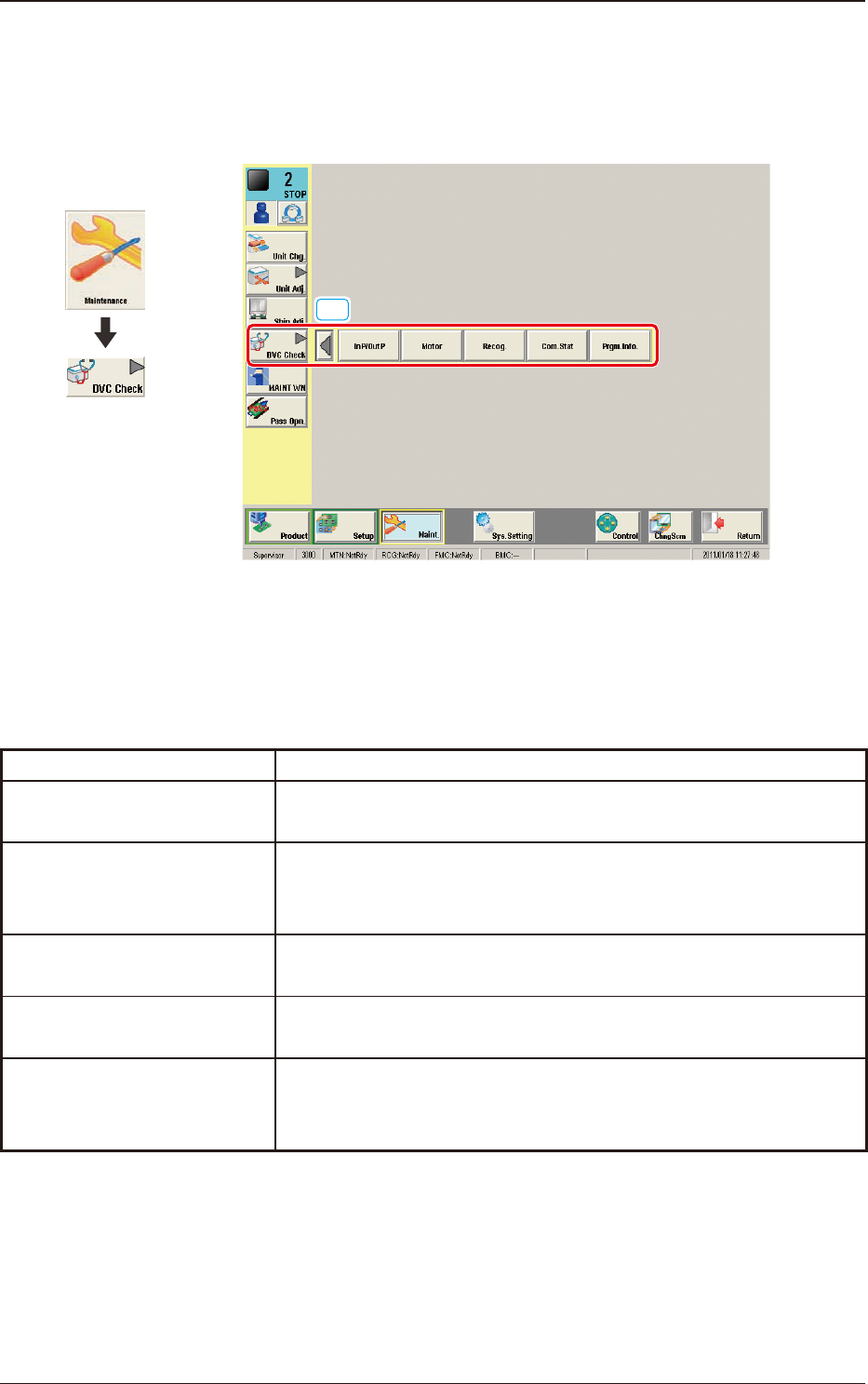
6. "DVC Check" Submenu
The corresponding window enables you to check the I/O signals and view the
status of each section.
[1]
F3A48
[1] "DVC Check" Submenu
The following buttons are arranged to display the operation windows for
executing each function for the device check.
Function Selection Buttons Description
In P/Out P
When pressed, the "INP / OUT" window opens, enabling you to
check the I/O status of each section.
Motor
When pressed, the "MOTOR" window opens, enabling you to
perform a manual operation (inching) of each unit and view the
current system information.
Recog.
When pressed, the "RECOG" window opens, enabling you to check
the I/O signals for the component and PEC recognition operations.
Com.Stat
When pressed, the "COM.STAT" window opens, enabling you to
check the communication status of each section.
Prgm.Info.
When pressed, the "PRGM.INFO." window opens, enabling you to
view the current program information and setup logs used for the
machine.
T3A5
Graphic
Development
6. "DVC Check" Submenu