3OM-1751-002w_G5S.pdf - 第191页
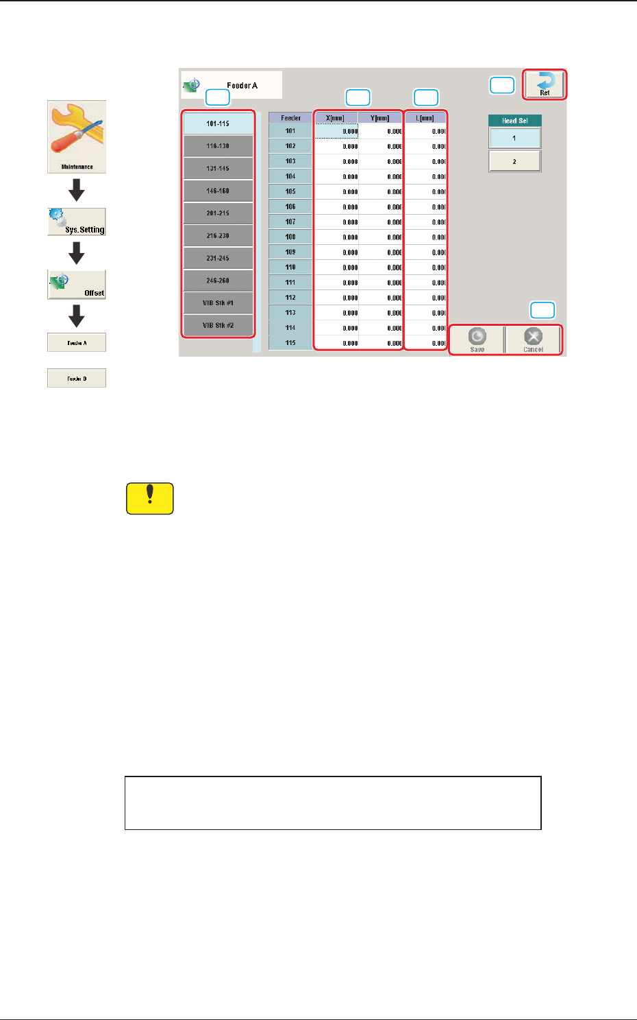
3OM-1751 2-23 1303-001 2.3 "Feeder A" and "Feeder B" Window [1] [2] [3] [4] [5] F3B23 Feeder Offset A This offset data is used to correct variation in each feeder slot (Fdr No.) of the feeder base. No…
3OM-1751
2-221303-001
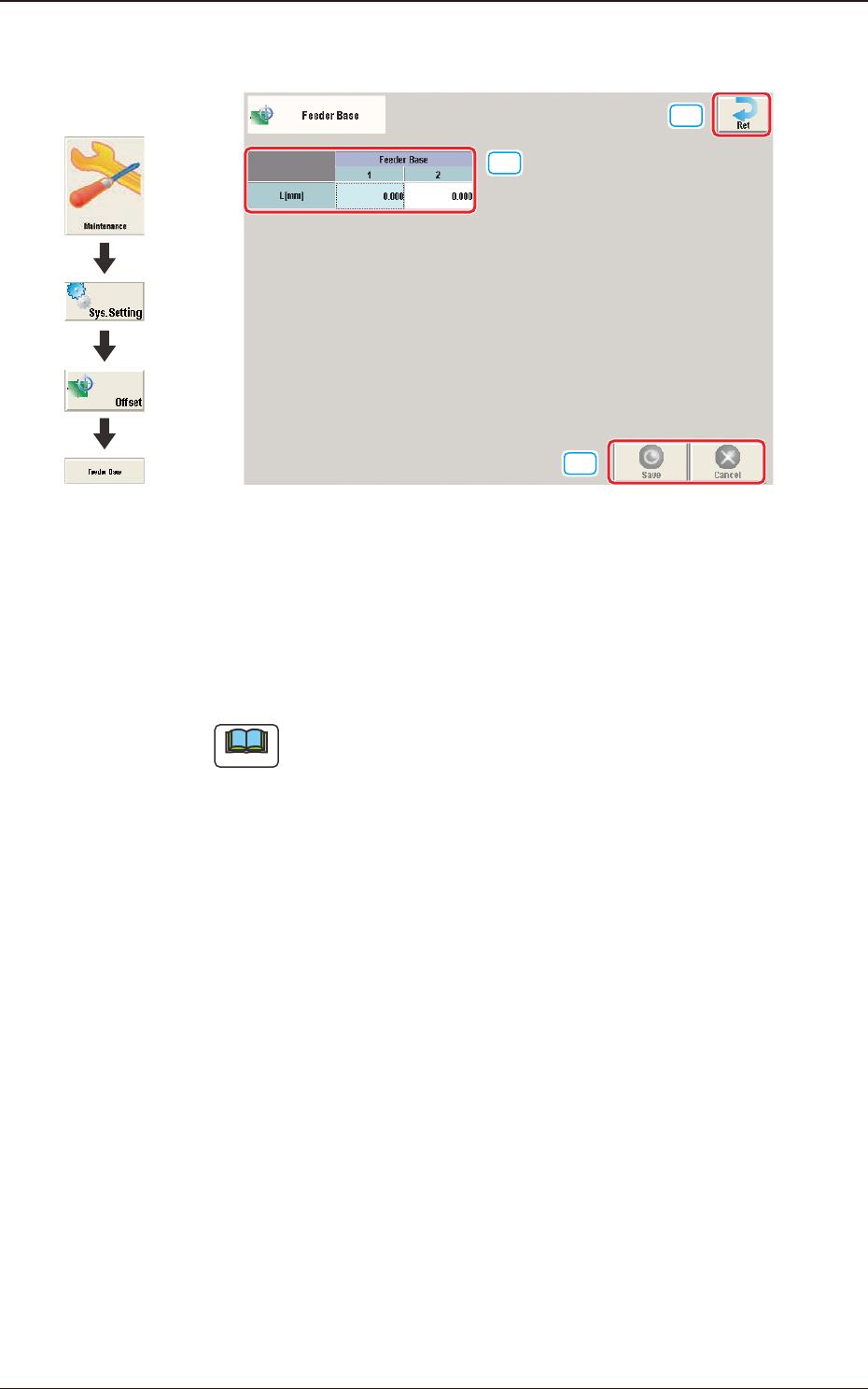
2.2 "Feeder Base" Window
[1]
[2]
[3]
F3B22
[1] L [mm]
The set offset parameters are used to adjust the positional deviations (height
direction) based on the design dimensions of Feeder Bases #1 and #2.
When the feeder bases are installed lower than the design values, a plus
value must be entered in each text box.
Note
The tilts of the PCB positioning sections on the feeder base sections are
calculated on the X and Y values of "Mark (Left)" and "Mark (Right)"
[2] [Ret] button
When this button is pressed, the "Offset Data" window is returned.
[3] [Save] button
When this button is pressed, the input data is applied.
[Cancel] button
When this button is pressed, the input data is cancelled and the save data is
returned.
2.2 "Feeder Base" Window
Graphic
Development
3OM-1751
2-231303-001
2.3 "Feeder A" and "Feeder B" Window
[1]
[2] [3]
[4]
[5]
F3B23
Feeder Offset A
This offset data is used to correct variation in each feeder slot (Fdr No.) of the
feeder base.
Notice
The parameters measured at shipment of the machine are entered.
Do not change the parameters unless necessary.
Feeder Offset B
This offset data is used to correct variation in the feeder.
•
The X and Y parameters are recognition-processed during the automatic
operation to track the positional relation between the nozzle and component
centers and updated automatically for better pickup posture (pickup on the
component center).
Note: In normal cases, it is not necessary to enter any parameters.
•
The "L [mm]" parameters are not updated automatically but the entered ones
are reected.
Feeder offset parameters are added to actual offset values.
Actual Offset Values = Feeder (A) Offset + Feeder (B) Offset
[1] Feeder Change Tab
Another tab sheet can be opened by pressing the corresponding "Feeder
Base" tab.
2.3 "Feeder A" and "Feeder B" Window
or
Graphic
Development
3OM-1751
2-241303-001
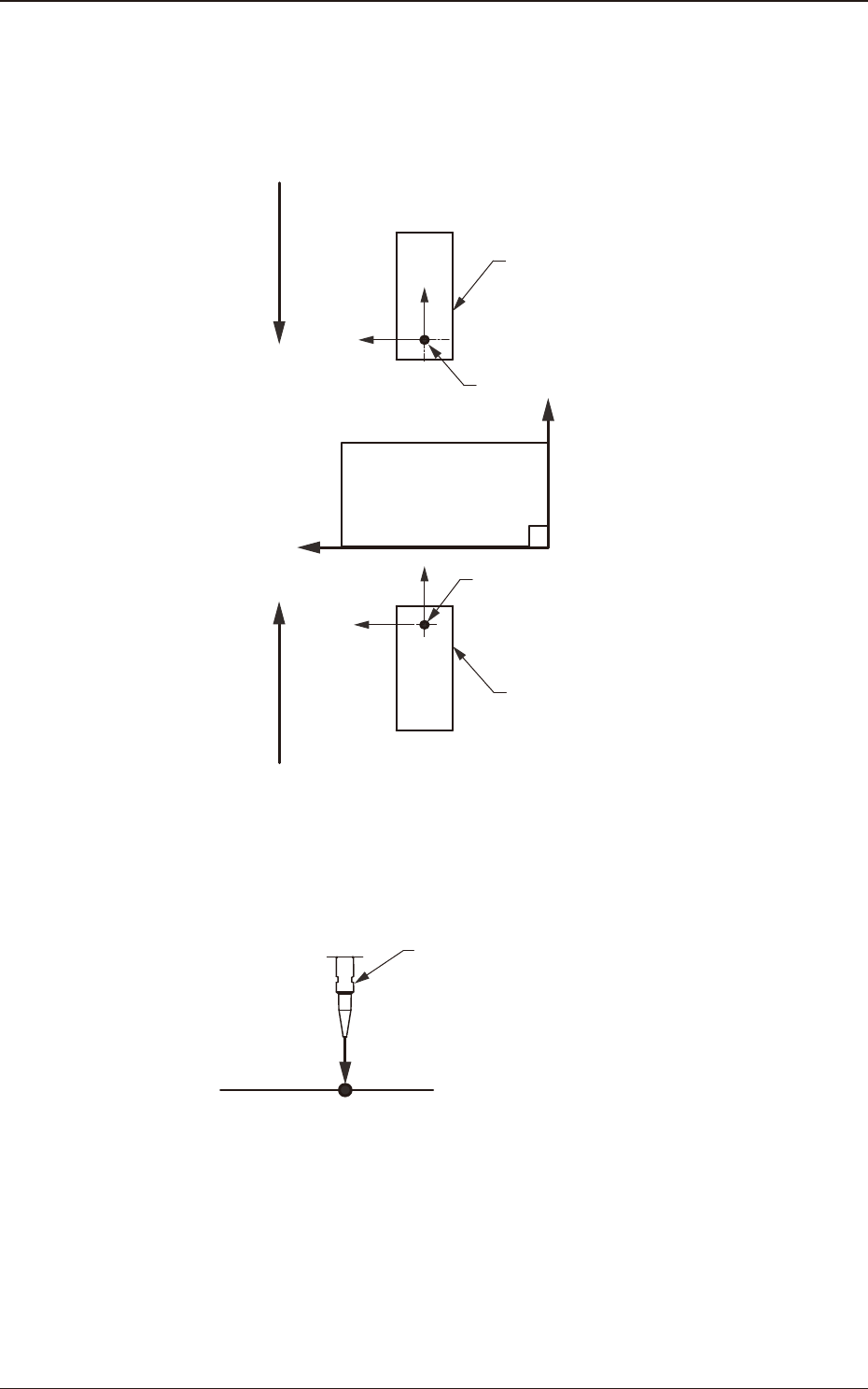
[2] X (Horizontal) and Y (Vertical) [mm]
These offset parameters are used to adjust the positional deviation based on
the design dimensions representing the component pickup position for each
individual feeder slot Nos. (Fdr Nos.).
F211
F111
Rear Feeder
Front Feeder
Front Side of Machine
Y(+)
X(+)
Pickup Position
Pickup Position
Direction of Tape Feed
Direction of Tape Feed
F3B24
[3] L (Height) [mm]
Pickup Reference Level
Nozzle
L(+)
F3B25
When a value is entered with a plus (+) sign, the pickup height is reected on
the direction in which the descending stroke of the nozzle will increase.
2.3 "Feeder A" and "Feeder B" Window