3OM-1751-002w_G5S.pdf - 第198页
3OM-1751 2-30 1303-001 2.5 "Head" Window [1] [2] [3] [4] [4] F3B30 [1] Of fset button When this button is pressed, the offset data for the selected tab is displayed. [2] Of fset Data Display Section In this sec…
3OM-1751
2-291303-001
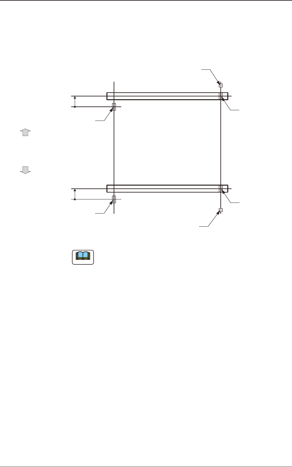
[4] XY-Axis Origin 1 and 2
The set parameters are used to maintain the beam condition (position) set up
right after the machine was assembled.
Use the values fed back automatically from the motion controller after the
Y-axis is zeroed (adjustment mode).
Master SideSlave Side
Origin Mark
(Origin Signal Position)
Beam
Beam
Zeroing
Direction
Zeroing
Direction
Y-Axis Origin Offset
= (+) Value
Limit Sensor
Y-Axis Origin Offset
= (+) Value
Origin Mark
(Origin Signal Position)
Origin Mark
(Origin Signal Position)
Origin Mark
(Origin Signal Position)
Limit Sensor
F3B29
Note
(a) The displayed parameters cannot be edited manually.
(b) The Y-axis origin offset indicates where the origin signal position of
the master axis is located when viewed in the zeroing direction from
the origin signal position of the slave axis.
A plus sign will be afxed when the origin signal position is located
in the same direction as the zeroing one. When it is located in the
opposite direction, a minus sign is afxed.
[5] Y-Axis Parallel Drive Origin
[6] [Return] button
When this button is pressed, the "Offset Data" window is returned.
[7] [Save] button
When this button is pressed, the input data is applied.
[Cancel] button
When this button is pressed, the input data is cancelled and the save data is
returned.
2.4 "Beam" Window
3OM-1751
2-301303-001
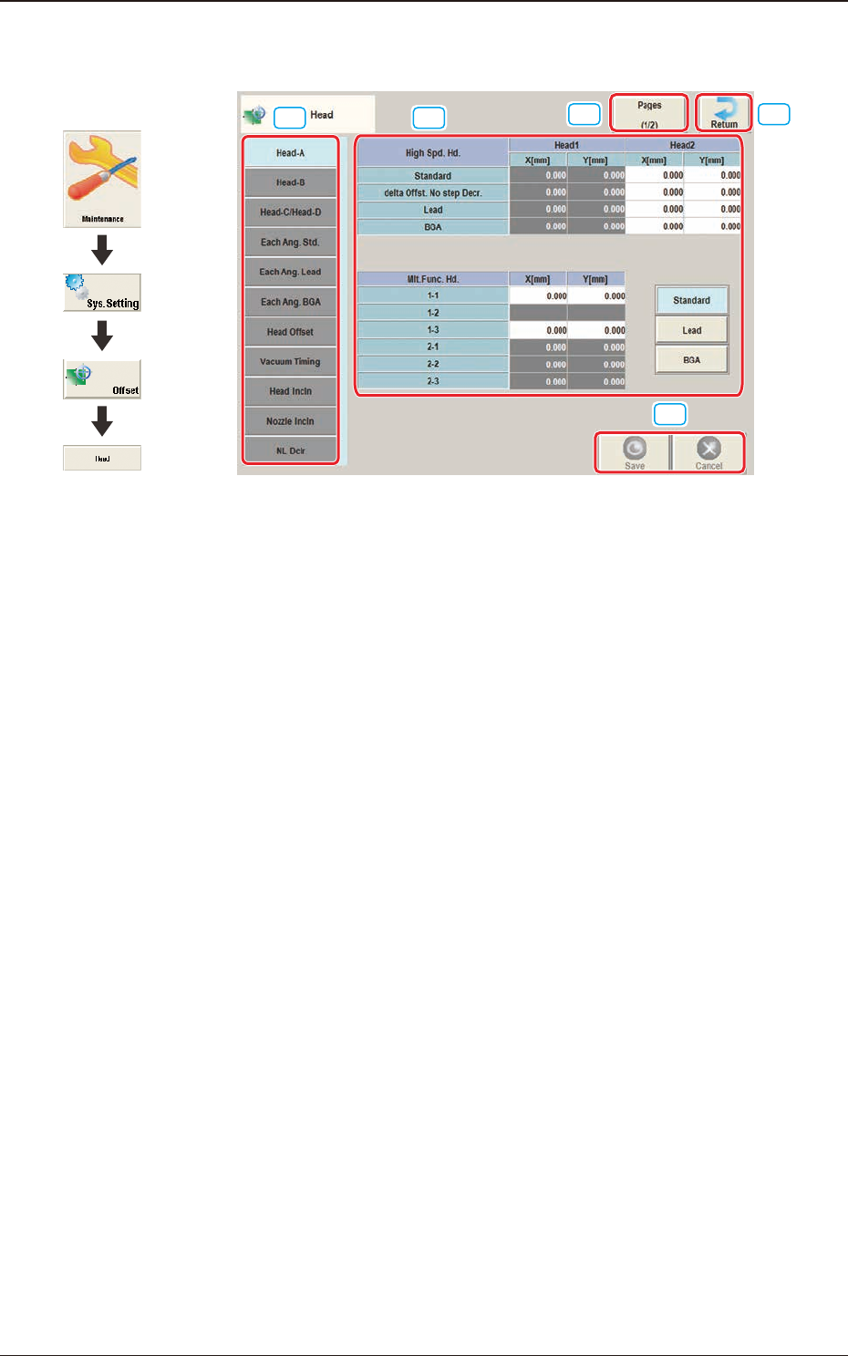
2.5 "Head" Window
[1] [2]
[3]
[4]
[4]
F3B30
[1] Offset button
When this button is pressed, the offset data for the selected tab is displayed.
[2] Offset Data Display Section
In this section, the offset data selected in step [1] is displayed.
[3] Page Change Button
Using this button, the offset editing page is changed.
[4] [Return] button
When this button is pressed, the "Offset Data" window is returned.
[5] [Save] button
When this button is pressed, the input data is saved.
[Cancel] button
When this button is pressed, the input data is cancelled and the save data is
returned.
Graphic
Development
2.5 "Head" Window
3OM-1751
2-311303-001
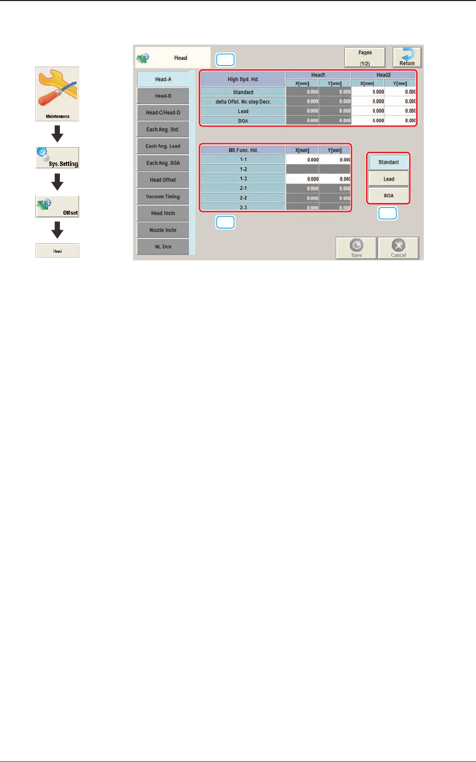
2.5.1 "Head-A" Tab Sheet
[1]
[2]
[3]
F3B31
[1] High Spd. Hd., Head 1 and Head 2
X [mm], Y [mm]
Standard
The set parameters are used to adjust the deviations of the head rotational
centers caused due to the movement of the head U/D axes.
delta Offst. No step Decr.
When no speed deceleration for component placement is specied in the
library data and the position for the placement is calculated, the proper
deceleration rate is converted and added.
Lead
When the library data set at the component placement is for the leaded
components, the value is converted or added in the placement target position
calculation using this button.
BGA
When the library data set at the component placement is for the BGA
components, the value is converted and added in the placement target
position calculation using this button.
2.5 "Head" Window
Graphic
Development