3OM-1751-002w_G5S.pdf - 第203页
3OM-1751 2-35 1303-001 2.5.4 "Each Ang. Std" T ab Sheet [1] [2] [3] [4] F3B34 [1] Nozzle 1 through 15 In this section, each nozzle No. is displayed. [2] Head 1 and Head 2 X (Horizontal) and Y (V ertical) [mm] W…
3OM-1751
2-341303-001
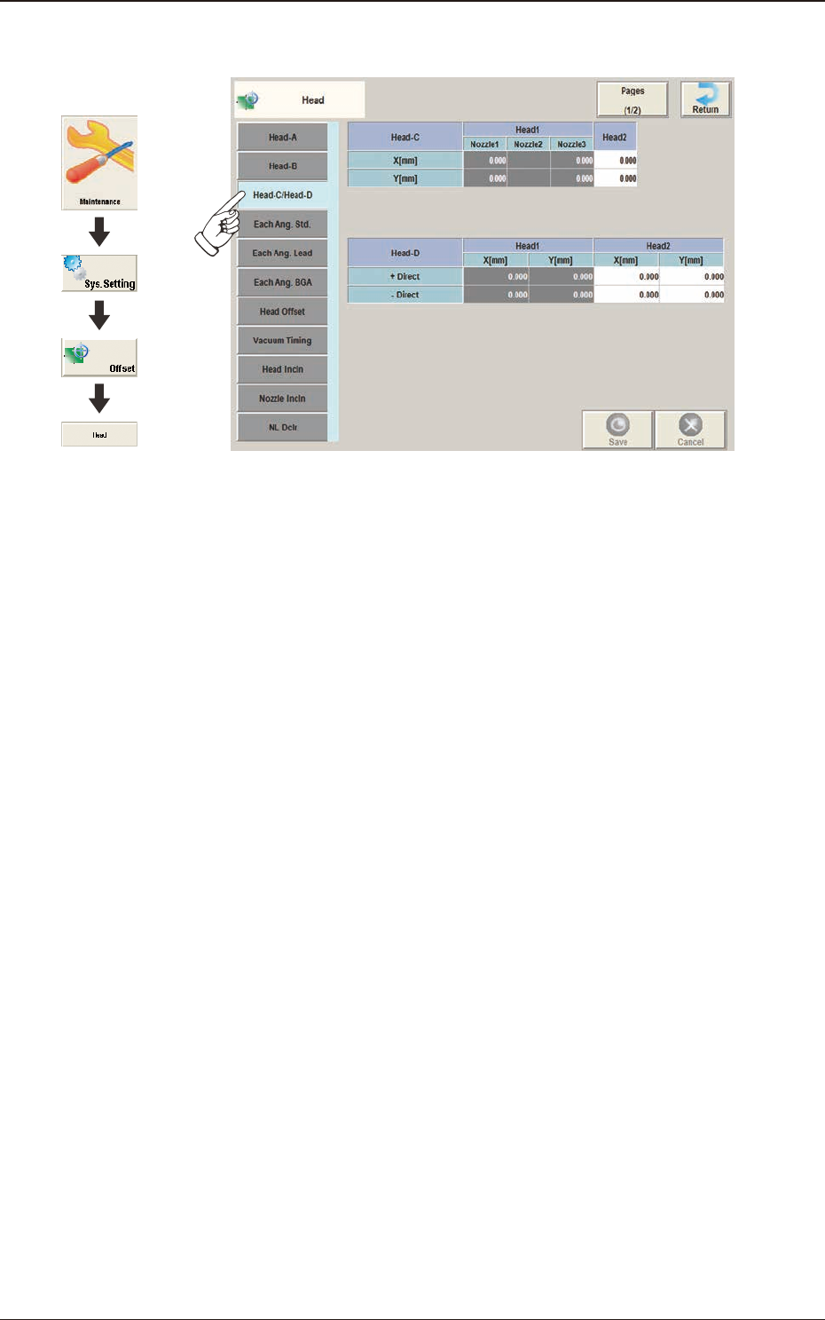
2.5.3 "Head-C/Head-D" Tab Sheet
F3B33
2.5 "Head" Window
Graphic
Development
3OM-1751
2-351303-001
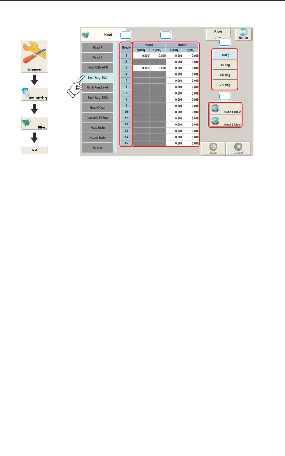
2.5.4 "Each Ang. Std" Tab Sheet
[1] [2]
[3]
[4]
F3B34
[1] Nozzle 1 through 15
In this section, each nozzle No. is displayed.
[2] Head 1 and Head 2
X (Horizontal) and Y (Vertical) [mm]
When the applicable component is a each angle one, conversion and addition
are made in response to the placement angle while the target position for
placement is being computed.
[3] Head Direction Selection Buttons
When this button is selected, the head direction is adjusted for each selected
angle.
[4] [Head 1 Clear] Button, [Head 2 Clear] Button
Using these buttons, the data parameters for all the nozzles in the
corresponding head are performed.
2.5 "Head" Window
Graphic
Development
3OM-1751
2-361303-001
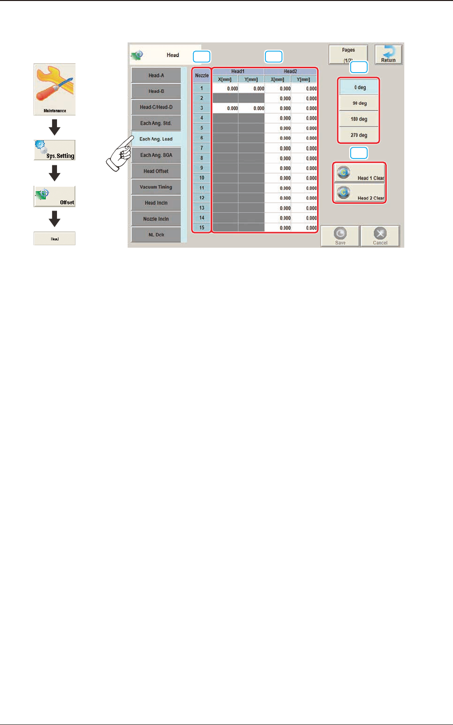
2.5.5 "Each Ang. Lead" Tab Sheet
[1] [2]
[3]
[4]
F3B35
[1] Nozzle 1 through 15
In this section, each nozzle No. is displayed.
[2] Head 1 and Head 2
X (Horizontal) and Y (Vertical) [mm]
When the applicable component is a leaded one, conversion and addition
are made in response to the placement angle while the target position for
placement is being computed.
[3] Head Direction Selection Buttons
When this button is selected, the head direction is adjusted for each selected
angle.
[4] [Head 1 Clear] Button, [Head 2 Clear] Button
Using these buttons, the data parameters for all the nozzles in the
corresponding head are performed.
2.5 "Head" Window
Graphic
Development