3OM-1751-002w_G5S.pdf - 第219页
3OM-1751 2-51 1303-001 2.6.3 "Nozzle up/dn" T ab Sheet [1] [2] F3B50 [1] Nozzle In this section, each nozzle No. is displayed. [2] Head 1 and Head 2 L [mm] Displayed is the offset data for the difference betwee…
3OM-1751
2-501303-001
[2] Head 1 and Head 2
X (Horizontal) and Y (Vertical) [mm]
Displayed is the offset data for the lowest levels of the normal nozzles on
the heads. The lowest level of each nozzle is measured by the component
recognition camera and the difference between the actual and recognized
levels is compensated for.
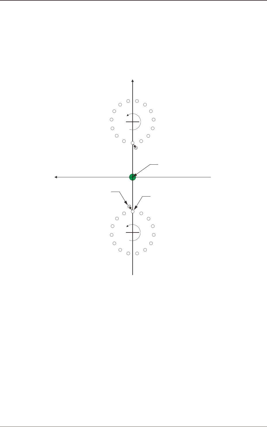
Xm(+)
Ym(+)
Xm-Ym :
DD (+)
DD (+)
Nozzle Designed Position
Real Nozzle Position
Pm. Machine Reference
Coordinate Origin
1
2
3
4
5
6
7
8
9
10
11
12
13
14
15
1
2
3
4
5
6
7
8
9
10
11
12
13
14
15
Machine Reference
Coordinate System
F3B49
2.6 "Nozzle" Window
3OM-1751
2-511303-001
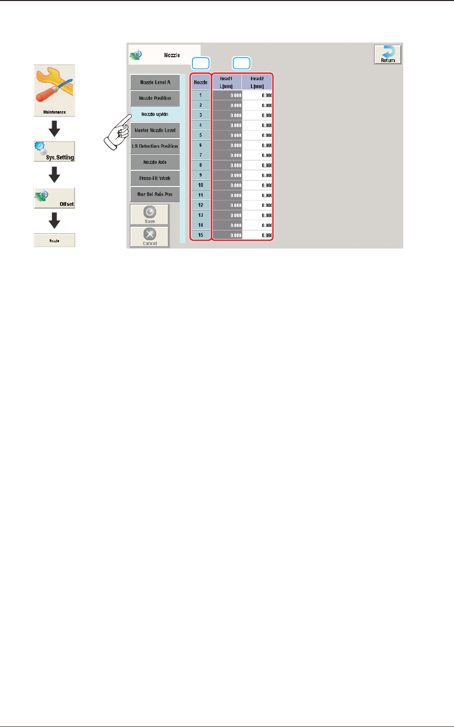
2.6.3 "Nozzle up/dn" Tab Sheet
[1] [2]
F3B50
[1] Nozzle
In this section, each nozzle No. is displayed.
[2] Head 1 and Head 2
L [mm]
Displayed is the offset data for the difference between the actually measured
value and designed value for the distance between the nozzle upper surface
and the nozzle up/down lever.
2.6 "Nozzle" Window
Graphic
Development
3OM-1751
2-521303-001
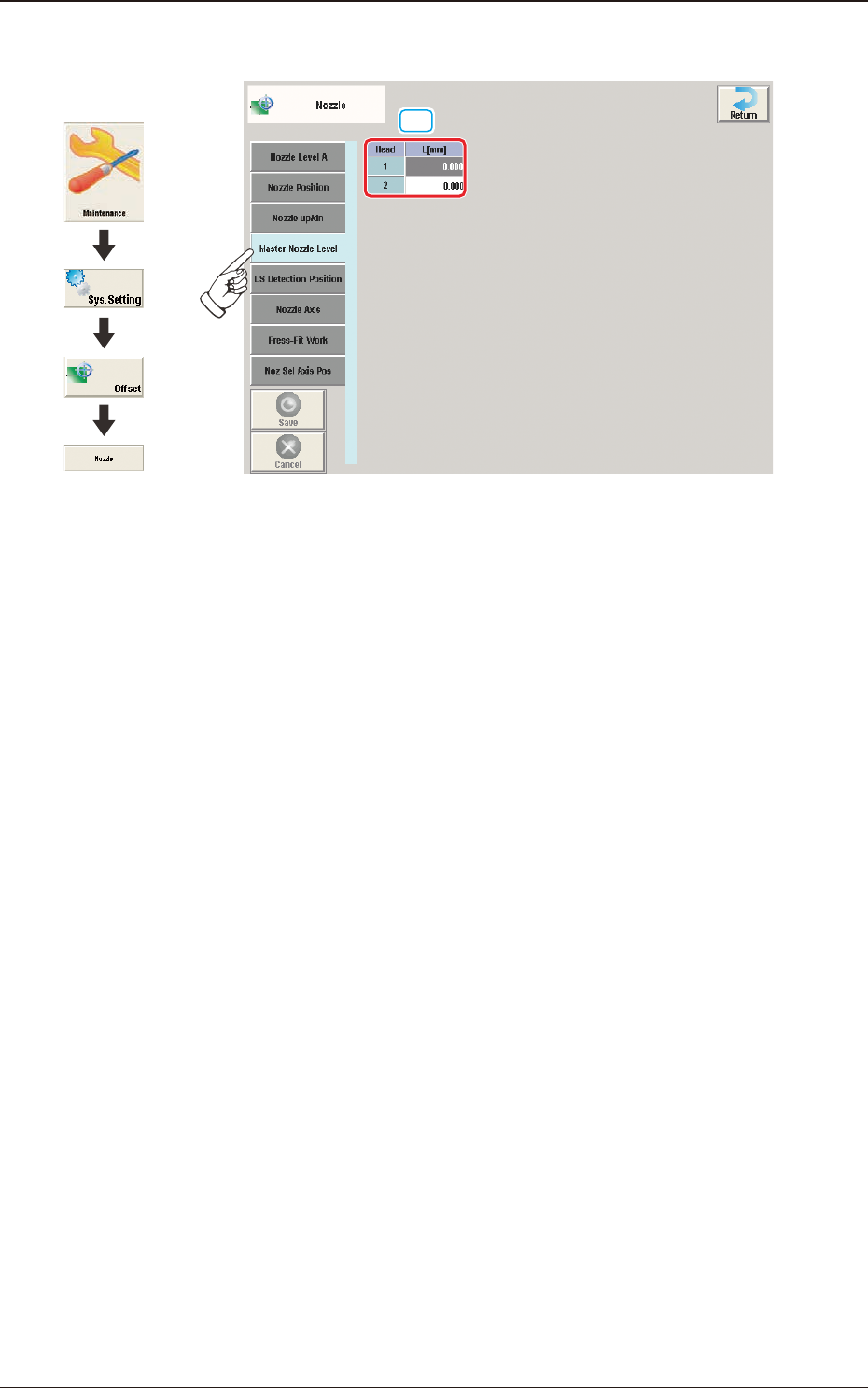
2.6.4 "Master Nozzle Level" Tab Sheet
[1]
F3B51
[1] Head 1 and Head 2
L [mm]
Each parameter indicates the reference position (the values read by the linear
measure) of the master nozzle bottom level.
Save the values of the master nozzle bottom level that was read by the linear
measure and used when the head up/down offsets were obtained with the
nozzle U/D axes being zeroed.
2.6 "Nozzle" Window
Graphic
Development