3OM-1751-002w_G5S.pdf - 第258页
3OM-1751 2-90 1303-001 [5] Line Machine Data Display Section Displayed is the data of line machine. Mc Name The machine name or IP address is set in this data box. Mc T ype The machine type is selected in this selection …
3OM-1751
2-891303-001
4.2 "Line Cong." Tab Sheet
[3]
[1]
[2]
[6]
[7] [8] [9]
Moving Cells
[4]
[5]
F3B80
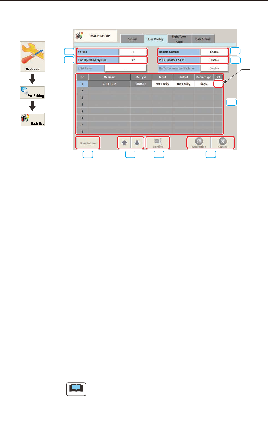
[1] # of Mc
The number of machines in the line is set in this text box.
[2] Line Operation System
The operation system in the line is selected from the following items and
setup.
Std
: Usually, this is selected.
LISA
: When the NA02001 LISA System Software SIGMA Series (Option)
is purchased and used, this is selected.
[3] PCB Transfer LAN I/F
Whether or not the LAN is to be used, is set up in this data box.
Enable
: When selected, LAN is enabled.
Disable
: When selected, LAN is disabled.
[4] Remote Control
"Enable" or "Disable" is set for the remote control operation from a machine
in the line.
Enable
: When selected, the remote control is enabled.
Disable
: When selected, the remote control (line start, etc.) is disabled from
a machine in the line.
Note
The PCB discharge operation, etc., is enabled.
4.2 "Line Cong." Tab Sheet
Graphic
Development

3OM-1751
2-901303-001
[5] Line Machine Data Display Section
Displayed is the data of line machine.
Mc Name
The machine name or IP address is set in this data box.
Mc Type
The machine type is selected in this selection box.
Input, Output
Whether the input machine and output machine are the associated machines
(SIGMA series) or non-associated machines, is selected in this selection box.
Sel
The machine to be re-arranged is selected in this selection box.
[6] [Send to Line] Button
When this button is pressed, the line conguration setup data is sent to the
machines in the line.
[7] Rearrangement Button
When this button is pressed, the machine arrangement order is changed.
After selecting the moving cell for the subject machine, re-arrange the
machine location using the [
] or [ ] button.
[8] [Conrm] Button
When this button is pressed, the machine selected in "[4] Line Machine Data
Display Section" is conrmed. When pressed, the tower lamp is turned ON
in the selected machine and buzzer sounds.
[9] [Application] Button
Using this button, the entered value is applied.
[Cancel] Button
When this button is pressed, the input data is cancelled and the saved data is
returned.
4.2 "Line Cong." Tab Sheet
3OM-1751
2-911303-001
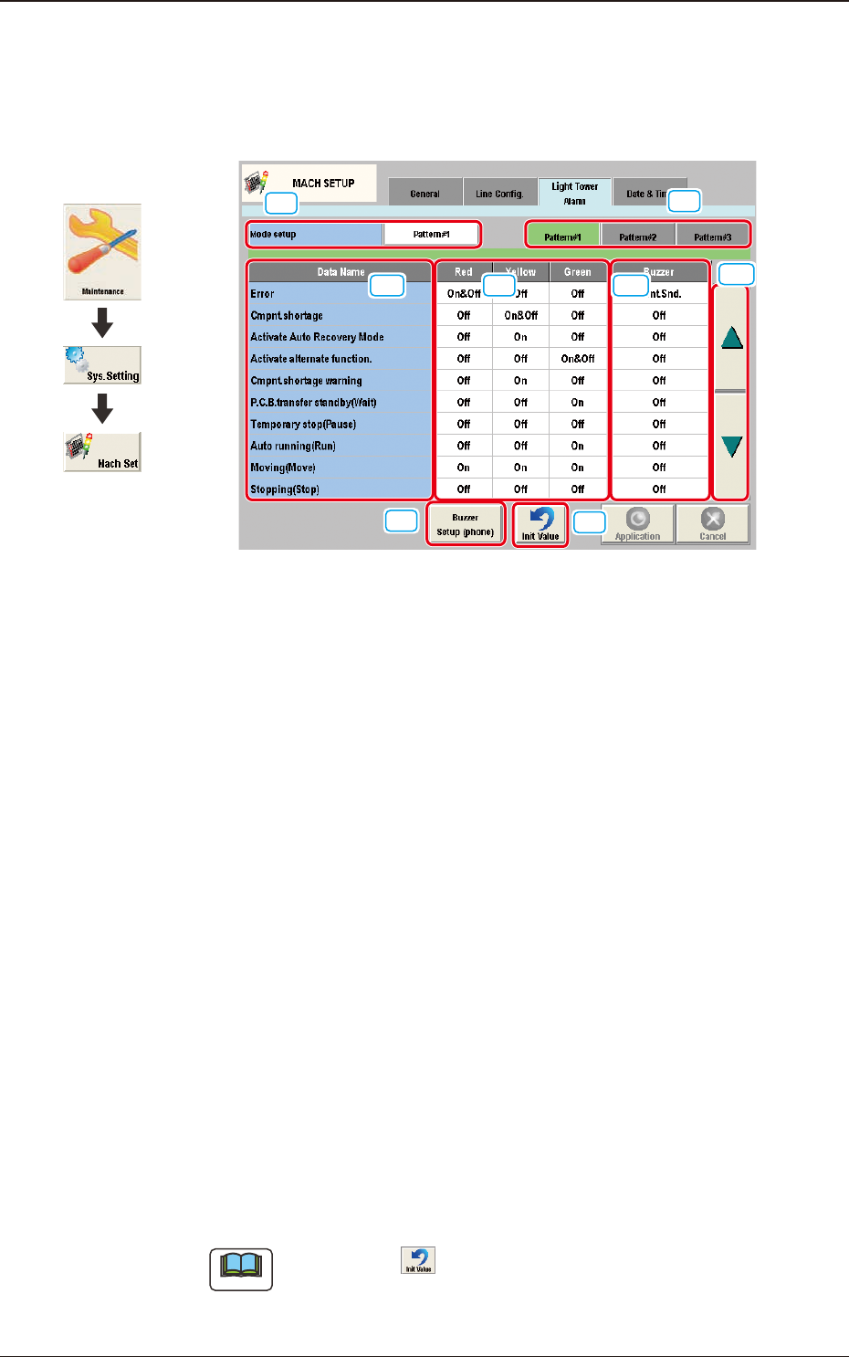
4.3 "Light Tower Alarm" Tab Sheet
The corresponding tab sheet enables the operator to allocate the lamp colors for
the light tower and the buzzer sounds.
[1]
[2]
[3]
[4]
[5]
[7]
[6]
[8]
F3B81
[1] Mode setup
The patterns are changed over.
[2] Tower Light ON/OFF Selection Buttons
[Pattern #1], [Pattern #2], and [Pattern #3] display buttons
These buttons can be used to change the setting of each tower light.
When one of these buttons is selected, the corresponding lighting pattern
appears, enabling you to change the settings.
[3] Data Name
Displayed are the items for which the colors (red, yellow, and green) of the
tower lights and the types of alarm sounds should be specied.
[4] Red, Yellow, Green
Set "On", "On&Off", or "Off" for the tower lights (red, yellow, and green).
[5] Buzzer
Set "Off", "Intmt. Snd.", "Cont. Snd.", or "Optl. phone" in each text box to
specify the types of alarm sounds.
The desired sound patterns can be made, using the [Buzzer Setup (phone)]
button.
Note
When the icon ( ) is pressed, the standard settings (defaults) resume.
4.3 "Light Tower Alarm" Tab Sheet
Graphic
Development