M4serviceManual_e.pdf - 第38页
3 Mechanical Section 3-8 Inspection for Head/Nozzle Clogging and Solenoid Valve Breakdown The following inspection m ust be carried out approxim ately once a week. ■ Inspection of Solenoid Valve The switching valve of th…

3 Mechanical Section
3-7
Head Manifold Section
■ Air Passage
To maintain the designed accuracy and component-placement rate of the machine, clean the air passage
between the air filter assy. and nozzle holder periodically.
ACTION: Carry out vacuum break operation for a few seconds with the nozzle removed.
● Cleaning interval
Approx. once a week
■ Air Filter
ACTION: Remove the filter element from the air filter assy. and remove dust and dirt collected inside the assy. by air
blowing. Then, check the white air element for dirt. If it is excessively dirty, replace it with a new one. If air
filter assy. case is dirty, wash it with water or diluted neutral detergent, and dry it well. If there are cracks on
the case, replace the air filter assy., since the cracks will cause air leakage.
NOTE: Do not use alcohol or any organic solvents to wash the air filter assy. case. Using those solvents may cause
damage or degradation of the case because it is made of polycarbonate.
● Inspection interval
Once a week, and when a choking error occurs
Part Name
Part No. Remark
FILTER ELEMENT LC1-M71A9-00X Filter element
AIR FILTER ASSY. LC1-M71A4-00X Air filter Assy.
■ Vacuum Generator
ACTION: Visually check the silencer element, and if it is excessively dirty, replace it with a new one. Also measure
the maximum air pressure to inspect whether the vacuum generator can generate vacuum properly.)
Inspection for Head/Nozzle Clogging and Solenoid Valve
● Inspection interval
Once a week
Part Name
Part No. Remark
SILENCER ELEMENT LG0-M71A8-00X Silencer element
GENERATOR,VACUUM LG0-M71A3-00X Vacuum generator

3 Mechanical Section
3-8
Inspection for Head/Nozzle Clogging and Solenoid Valve
Breakdown
The following inspection must be carried out approximately once a week.
■ Inspection of Solenoid Valve
The switching valve of the solenoid valve may catch foreign matter causing air leakage. Air leakage will
turn the suction ON even if it is turned OFF.
As a result, the suction cannot be turned OFF after a component is mounted, and components may be
returned instead of being mounted on the PCB.
● Inspecting by selecting [Manual] – [Meas. Air pressure]
①Checking the maximum air pressure
Turn ON the suction and press the head tip with fingers to check the air pressure. The air pressure is
satisfactory if it is “600” or higher.
②Checking the head for clogging
With no nozzles placed in the head, turn ON the suction to check the air pressure. Typical air pressure is
approx. “30”. An error will occur if the air pressure is “120” or higher during vacuum check performed
after nozzle replacement.
③Checking the nozzle for clogging
With nozzles placed in the head, turn ON the suction to check the air pressure. “Nozzle clog criteria” has
been set for each nozzle. The air pressure must be below the criteria. If it is not, the nozzle will be
considered to be clogged and an error will occur.
④Checking the solenoid valve for switching failure
Turn OFF the suction and check for change in the air pressure.
- Press the head/nozzle tip with fingers and check for change in the air pressure.
- Turn ON and OFF the suction a few times and check for change in the air pressure.
If the air pressure changes even though the suction is OFF, air is probably leaking from the suction solenoid
valve.
NOTE: Do not disassemble the solenoid valve. Manufacturer’s guarantee will be ineffective if the solenoid valve is
disassembled.
Part Name
Part No. Remark
SOL.VALVE LC1-M71A1-00X solenoid valve
NOTE: For official inspection, use of a digital vacuum meter is necessary to check accuracy of the displayed air
pressure value.
Part Name
Part No. Remark
MANOMETER ASSY. LC1-M89A5-00X Vacuum Gauge Set
3 Mechanical Section
3-9
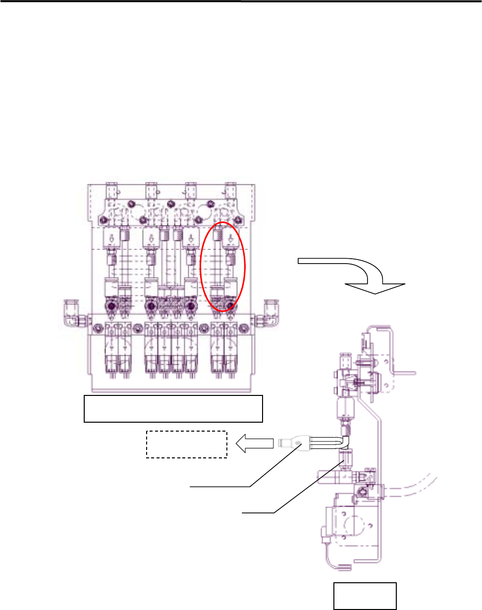
■ Checking by Vacuum Meter
Instead of using the machine’s air pressure measurement function, a digital vacuum meter can be used to
check the head’s maximum air pressure as well as that of the head and nozzle for clogging.
ACTION:
①Connecting a vacuum meter
Remove the air hose from the joint at the vacuum generator side, attach a branch joint and connect the
vacuum meter as shown below.
Head Manifold Section (Front View)
Joint (at the vacuum generator side)
Branch joint
Side View
Vacuum meter
*The Front View Illustration is for M4a, but the different with M4e/M4s is total head number only.
The Side View Illustration is same for both types of machine.
②Checking the maximum air pressure
Turn ON the suction and press the head tip with fingers to check the air pressure. The air pressure is
satisfactory if it is “0.08” MPa or higher.