M4serviceManual_e.pdf - 第58页
3 Mechanical Section 3-28 ■ Lubrication Poin ts for S-axis Ball Screw/Linear guide Backside of head S-axis ball screw S-axis linear guide NOTE: Greasing on the S-axis ball screw/linear guide shoul d be performed at backs…
3 Mechanical Section
3-27
NOTE: If too much grease is applied, excess grease may scatter around during machine’s running. Apply proper
amount so that thin coat of grease is made over the surface.
NOTE: If grease is applied on the ball screw surface (out of ditch), the grease will be coming out, not being caught
by ball bearing inside. That may cause insufficient lubrication condition. Then Apply grease onto the ditch
of the ball screw.
■ Lubrication Points for Linear Guide
ACTION:
① Wipe off the dirty grease or adhered grease on the linear guide. Use a nonwoven cloth to wipe, not a
cotton swab or woven cloth that may generate dust or waste threads.
② Push the grease gun to the grease nipple and apply grease in the linear guide nut.
Grease Gun
Grease Nipple
Y-axis Linear Guide
③ Perform “Ageing” in Manual > Warm Up with the less than 20% axis speed for more than 10 minutes.
Speed setting can be done by sliding the “Axis Speed” gauge at [Setting] tab.
④ Then wipe off the pushed-out dirty grease with a nonwoven cloth and apply new grease into the nut
again.
⑤ Remove excessive grease gathered on the nut or both ends of the ball screw with a nonwoven cloth,
and perform “Ageing” by increasing axis speed gradually.
⑥ By Axis command in Manual Menu, move the Head Assy. from an end of axis to the other end for
several times, so that the applied grease is spread over whole of the work range. However, the spread
grease cannot reach the actual end of each axis because of the out of work range of the nut. Then add
some grease there by hand with a nonwoven cloth etc.
NOTE: If a cotton-swab or a woven cloth is used to wipe off the dirty grease, waste threads of cloth may be caught
in the ball screw. Use a nonwoven cloth.
NOTE: Use proper grease for lubrication, specified as our standard. (See the “Specified Lubricants” list at the end
of this chapter.)
NOTE: Remove the excess grease gathered on the nut or both ends of the ball screw by wiping it off with a
nonwoven cloth to avoid grease scattering.
3 Mechanical Section
3-28
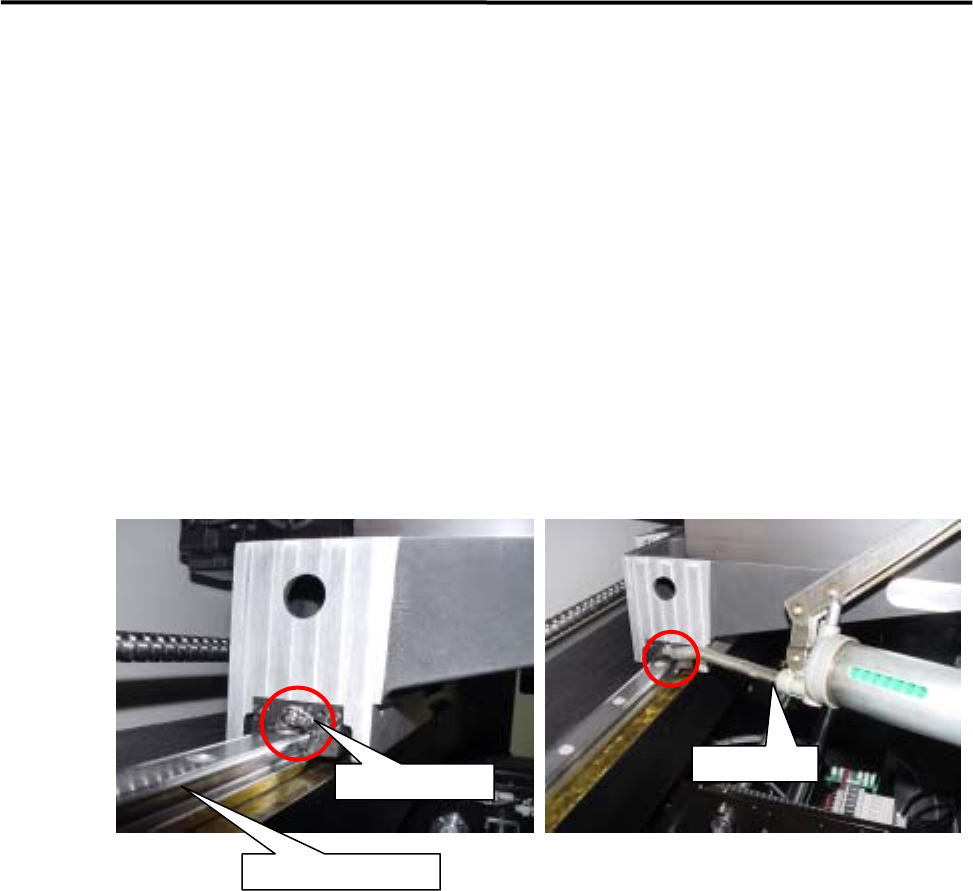
■ Lubrication Points for S-axis Ball Screw/Linear guide
Backside of head
S-axis ball screw
S-axis linear guide
NOTE: Greasing on the S-axis ball screw/linear guide should be performed at backside of the machine.
M4a has the backside cover attached, and it should be removed in advance to the job.
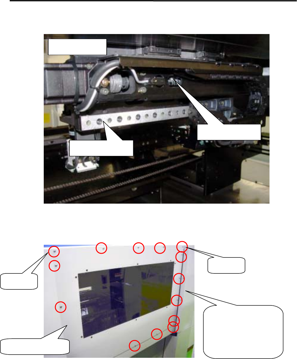
Backside cover (M4a)
There are 18 screws fixing on
the backside cover. When
taking out of the backside
cover, follow the procedure
of [NOTE] below.
Setscrew-B
Setscrew-A
NOTE: Because of the structure of the backside cover, it is very dangerous to remove all setscrews from the cover,
causing the cover falling down. Follow the procedure below to take out the backside cover.
① Remain the two setscrews on both ends of upper position (Setscrew-A/B), and remove all the other
setscrews.
② Loosen the setscrew-A/B for 1 turn around. (Remain the setscrews without removing.)
③ Hold the backside cover upward, and pull it carefully to your side to remove it.
* Installation of the backside cover must be carried out in reverse order of removal.
3 Mechanical Section
3-29
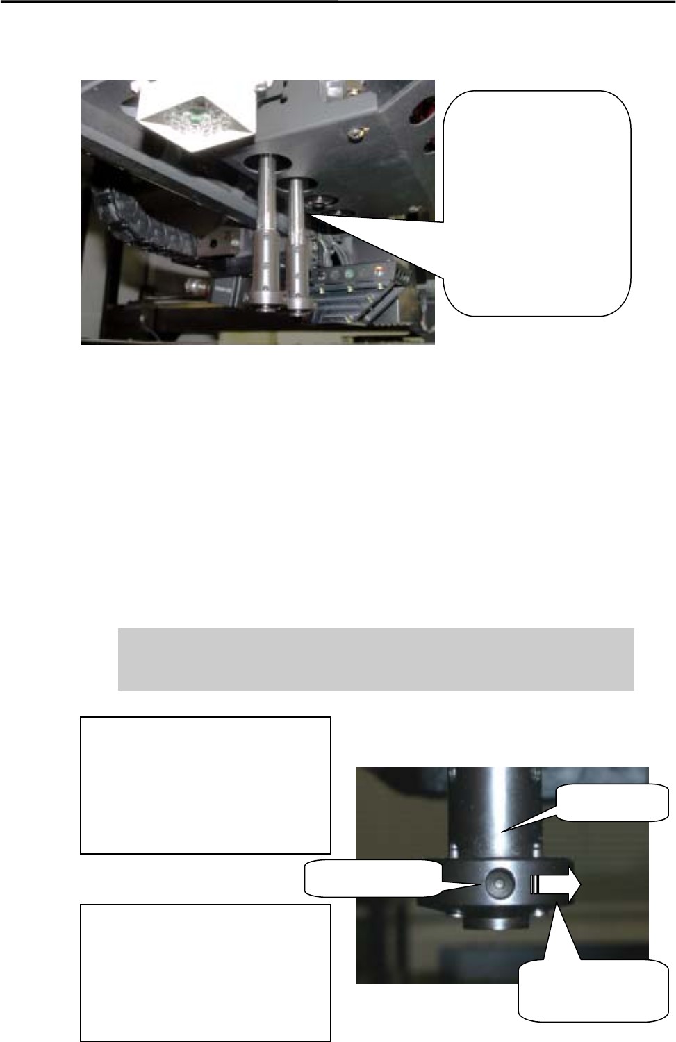
■ Lubrication Points for Spline Shaft
Spline Shaft:
Turning off the servo motor
power, each head can be
pulled down manually. Pull
down each head until the
spline shaft part appears as
seen on left, and applying
grease can be easily
performed.
NOTE: For the procedure to turn off the servo motor power, see the iMS Operation Manual, Chapter 7, Servo Off.
NOTE: With each head in down position, do not manually move X /Y/S axis , neither set feeder on the feeder bank
or remove it off because that may cause head collision with other part such as conveyor, feeder, lighting
box of scan camera. When any heads pulled down manually to apply grease, the heads must be up before
starting the other operation, by manually pushing them up to Z axis origin around or performing
Return-to-origin for Z axis with Servo On.
NOTE: If R-axis (Theta axis) is rotated by hand during machine power OFF or Servo OFF condition, the R-axis
origin may shift 180 degrees away after the Origin Initialization. If you rotated R-axis by hand during
lubrication, be sure to check the R-axis orientation after Origin initialization. If the orientation is not correct,
adjust it by following steps. In case of M4e/M4s, this problem would3-27 not occur.
If machine is operated under the R-axis origin with 180 degrees shift, several
problems may occur such as Nozzle broken, abnormal machine stop at Auto
Nozzle Change, and Scan Camera broken (mirror or lighting unit).
Rotating direction of
Nozzle holder
How to adjust R-axis origin position;
1) Under the Servo OFF condition, rotate
the Nozzle holder to right direction for
two turns.
2) Perform “Origin” command, and check
that the R-axis faces to correct orientation.
Nozzle holder
Hole of Origin-sign
How to check R-axis origin position;
After returning R-axis to Origin, check
that the hole of origin-sign on the Nozzle
holder faces to machine front.
That is the correct orientation of R-axis at
origin.