M4serviceManual_e.pdf - 第72页
4 Electrical Section 4-6 Adjustment of Board Detection Sensors This section explains h ow to adjust th e sensitivity of the b oard detection sens ors. ● LC1-M90H3-00X PHOTO SENSOR E3Z-D61 (OMRON ) z Entrance sensor z Exi…
4 Electrical Section
4-5
Electrodes on Feeder / Feeder Bank
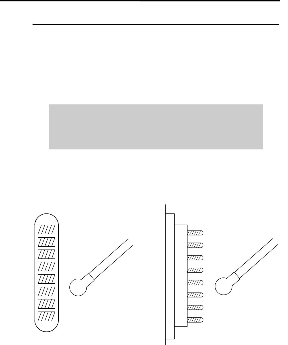
When electrodes on the feeder bank and the tape feeder get dirty, clean them as follows:
NOTE: If the electrodes are touched by hand or have come into contact with foreign matter, cleaning is
recommended even if no dirt can be observed visually.
ACTION: Clean the electrodes by wiping off dust gently with a dry cotton swab or non-woven fabric. When cleaning
them, check that the pins are not bent. If they are bent excessively, contact i-PULSE for repair. Continuing
to use them if the pins are bent may scratch the contact surface of the feeder bank.
Do not use alcohol, water base detergents and organic solvent, such as
thinner, benzene and acetone.
Do not use sandpaper and tools with sharp blade or edge, such as a knife and
a screwdriver.
NOTE: If they get stubborn stains, try not to get rid of them forcedly. Please contact us.
Cotton swab
Pin Electrodes on feederElectrodes on feeder bank
Cotton swab
4 Electrical Section
4-6
Adjustment of Board Detection Sensors
This section explains how to adjust the sensitivity of the board detection sensors.
● LC1-M90H3-00X PHOTO SENSOR E3Z-D61 (OMRON)
z Entrance sensor
z Exit sensor
z Exit buffer arrival sensor
■ Adjusting Method
① Place a PCB on the conveyor belt in the direction in which PCBs will be placed for actual production
operation.
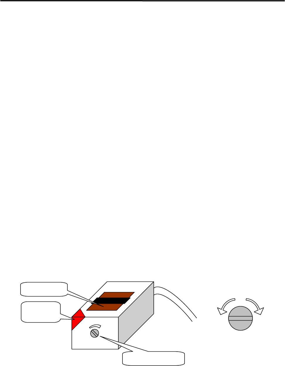
② Turn the sensor’s sensitivity volume counter-clockwise (toward “min”) as far as it will go, to set the
sensitivity to the minimum level.
*The volume can be turned 3/4 turns. Turning it clockwise (toward “max”) increases the sensitivity
and turning it counter-clockwise (toward “min”) decreases it.
③ With the PCB detected by the sensor, turn the volume clockwise (toward “max”) gradually, up to the
point (A) where the orange LED (operation indicator) begins to light up.
④ Remove the PCB and turn the volume clockwise (toward “max”), up to the point (B) where the orange
LED begins to light up. (If the orange LED does not light up even if the volume is turned clockwise as
far as it will go, the position to which the volume has been turned clockwise as far as it will go will be
considered to be position (B).)
⑤ The center position between the positions (A) and (B) is set as the adjustment position. With the PCB
detected at that position, check that both orange and green LEDs light up at the same time. Also check
that only the green LED lights up when the PCB is removed.
⑥ When the conveyor cover is provided because of the safety spec., attach a black rubber sheet to the
sensor detection position on the bottom of the cover to prevent false detection.
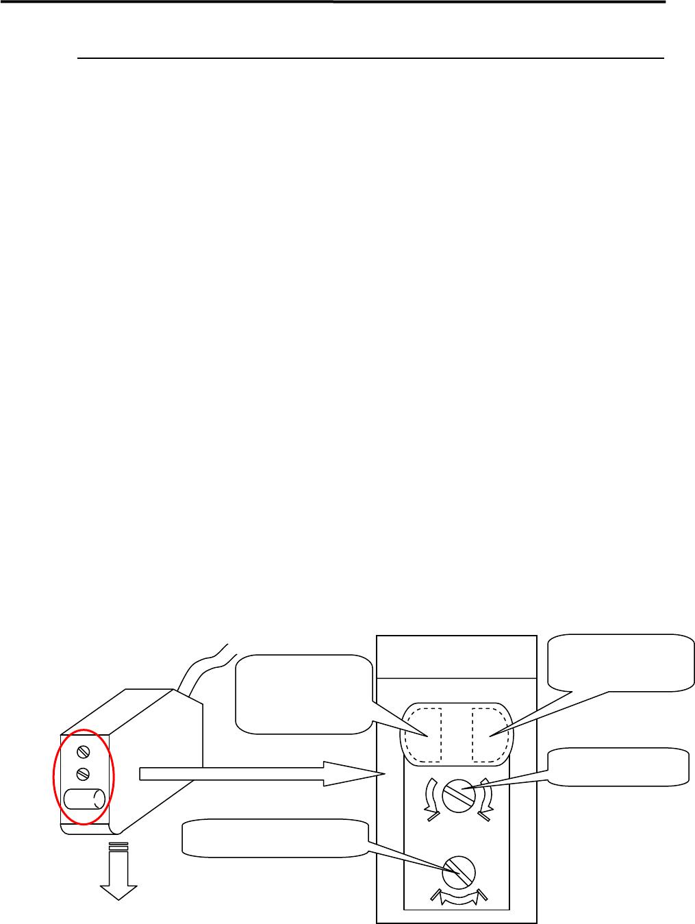
NOTE: Make sure that the operation selector switch is set to “L” (ON when light is entered).
Operation selector switch
Sensitivity volume
Operation-stable
indicator
(Green LED)
Operation indicator
(Orange LED)
Sensor emitting direction
DL
min max
Enlarged View of Sensor
(Shown in upside down
direction)
4 Electrical Section
4-7
● LG9-M90H6-00X PHOTO SENSOR WT4-2N112S28 (SICK)
z PCB arrival sensor
z Entrance buffer arrival sensor
■ Adjusting Method
① Use a precision flat-blade screwdriver to turn the sensitivity volume counter-clockwise as far as it will
go, to set the sensitivity to the minimum level. Place a PCB on the conveyor belt in the direction in
which PCBs will be placed for actual production operation, transfer it to a position just over the arrival
sensor, and turn the sensitivity volume clockwise until the sensor’s receiver indicator lights up.
NOTE: The sensitivity volume can be turned approx. five turns between the maximum and minimum level
positions. When the volume is beyond the maximum or minimum level position, a ratchet will be activated
and the volume turns freely with a chattering sound. The position at which such sound is heard is the limit
of the adjustable range.
② With the PCB placed on the conveyor belt, move it just above the arrival sensor back and forth a few
times by hand, to check that the receiver indicator turns ON and OFF in response to the PCB.
NOTE: The receiver indicator has three states: ON = stable operation, OFF = no sensitivity, Blink = unstable
operation. When adjusting the volume or checking sensor’s response to the PCB, make sure that the
indicator is not blinking.
③ From position (2), turn the volume 1/4 turns (90 degrees) clockwise to increase the sensitivity.
④ For verification, select [Manual] – [PCB Sensors ] to open the [PCB Sensors ] window. Check that the
PCB arrival sensor/entrance buffer arrival sensor respond to the PCB correctly. Also select [Manual]
– [Load Board ] to check that the PCB is automatically clamped properly.
NOTE: If the sensitivity is set excessively high, a malfunction may occur when the head passes over the arrival
sensor.
Receiver
indicator
Sensitivity Adjustment
by Volume
Higher
sensitiv
Lower
sensitiv
Sensitivity volume
Emitter/receiver