Specification SIPLACE X-Series S 规格说明书 - 第42页
42 SIPLACE Vision Barcode types Technical data 1D barcode s QR codes Code typ es Code 39 Code 93 Code 128 EAN-8 (AddOn 2, AddOn 5), E AN-13 (AddOn 2, AddOn 5) Interleaved 2 of 5 (station so ftware version 709.1 or higher…

41
SIPLACE Vision
Barcode types
Technical data
The PCB camera can read a
Data matrix code, a 1D bar-
code or a QR code. The
data can be used for trace-
ability purposes.
The barcode can be on the
board itself or on a compo-
nent. In addition, it is also
possible to attach a barcode
label to a board or a compo-
nent and to then read this
barcode label with the PCB
camera, directly after place-
ment. The focal height must
be taken into account during
reading, if there is a barcode
or barcode label on the top of
a component.
General information for all barcode types
Data matrix codes
Ambiguity No read errors are issued if multiple valid barcode symbols are found in a
particular region of interest (ROI). In this case, there is no clear rule, defin-
ing which of these valid barcode symbols would be read.
Ambiguity can be avoided by:
• Using a suitable ROI size
ASCII null characters Barcode information should not contain any ASCII null characters (ASCII
NULL), as the 0 byte in the software is interpreted as an final (end) char-
acter.
Code type Only data matrix ECC 200 is supported.
No. rows/columns All combinations of rows/columns as defined in the standard will be
accepted, including rectangular symbols and large symbols with multiple
data areas.
Minimum dot size 5 pixels.
Symbol angle All symbol angles will be accepted.
Inverse symbols Inverse symbols (light modules on a dark background) will be accepted.
Mirrored symbols Mirrored symbols will be accepted.
Ratio of column width to row
height
1/2
≤ (column width) / (row height) ≤ 2
Region of Interest (ROI) The area in which the barcode is searched for (ROI) should not exceed the
following values:
Width of ROI
≤ 6 * width of barcode symbol
Height of ROI ≤ 6 * Height of barcode symbol

42
SIPLACE Vision
Barcode types
Technical data
1D barcodes
QR codes
Code types Code 39
Code 93
Code 128
EAN-8 (AddOn 2, AddOn 5), EAN-13 (AddOn 2, AddOn 5)
Interleaved 2 of 5 (station software version 709.1 or higher required)
Minimum width of bar 5 pixels.
If the quality of the mark is sufficient, the width can be reduced down to 3
pixels.
Minimum height of symbol 5% of length of whole symbol.
Symbol angle All symbol angles will be accepted.
Inverse symbols Light bars on a dark background will be accepted.
(Station software version 708.0 or higher required)
Mirrored symbols Mirrored symbols will be accepted.
(this corresponds to a rotation of 180 degrees for 1D codes)
Region of Interest (ROI) The area on the board, in which the barcode is searched for (ROI), should
not exceed the following values:
ROI (direction of reading)
≤ 3 * symbol width
ROI (vertical to direction of reading) ≤ 10 * symbol width
Code type QR code in accordance with ISO/IEC 18004 model 2.
Station software version 711.0 or higher required
No. rows/columns All versions still defined in the standard (i.e. number of rows/columns) are
accepted.
Minimum dot size 5 pixels.
Symbol angle All symbol angles will be accepted.
Inverse symbols Inverse symbols (light modules on a dark background) will be accepted.
Mirrored symbols Mirrored symbols will be accepted.
Ratio of column width to row
height
1/2
≤ (column width) / (row height) ≤ 2
Region of Interest (ROI) The area in which the barcode is searched for (ROI) should not exceed the
following values:
Width of ROI
≤ 6 * width of barcode symbol
Height of ROI ≤ 6 * Height of barcode symbol
43
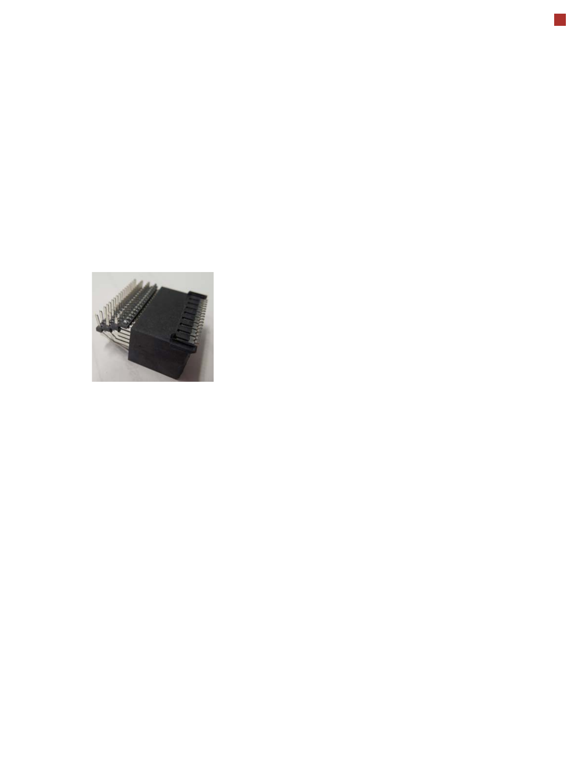
OSC package
The licensed OSC package
contains functions for simpli-
fied placement of odd
shaped components (OSC),
such as connectors or sock-
ets.
The license is activated via
SIPLACE PRO.
For detailed information,
refer to the OSC package
user guide, item number
[00198374-xx].
The following functions are
contained in the OSC pack-
age:
OSC measurement options
• Customized odd shaped
component
This enables the user to
describe any abstract pat-
tern on a component e.g.
connection leads of a tri-
angular shape. This pat-
tern can then be easily
created and edited at the
station, using the wizard
function.
• Stereo measurement
Stereo measurement
means that two images
are taken of each compo-
nent, from different direc-
tions, using a stationary
camera. These images
are overlapped to show
connectors, pins etc. in 3D
to support easy and pre-
cise evaluation of struc-
tures which, due to color,
shading or background
structures, are difficult to
recognize in conventional
2D measurement.
• Special position evalua-
tion
This function supports
separate definition of posi-
tion-determining features
(x,y, angle) independent
of the features for good-
bad recognition.
Placement of snap-in com-
ponents
This function monitors
whether snap-in components
engage in the board prop-
erly, during automatic place-
ment.
Pin in paste height check
This option extends the
"snap-in" function for CPP
and Twin heads.
Automatic calculation of
optimum acceleration
This function enables the
user to automatically calcu-
late the optimum accelera-
tion of individual axes for a
component at the station.
The acceleration values
found can then be checked in
an additional test run and
sent back to the program-
ming system if successful.
Placement of very high
components
In special application cases
the software can place a very
high component with auto-
matic collision prevention.
Additional force levels for
TH and CPP head
•30 N for TH
• 15 N for CPP
15.5 mm high components with CPP restrictions
• The maximum height of 15.5 mm can only be reached if the
PCB warpage upwards is 0 mm (setting in SIPLACE Pro).
• NO SIPLACE TwinStar permitted anywhere in the line.
• If there are two SIPLACE MultiStars (CPP) in the same
placement area, only one CPP can place components up to
15.5 mm.