00197973-10_SM_MaterialTower.pdf - 第162页
Gripper 0019797 3 - 10 / 02 , 2016 7- 44 © ASM SIPLACE Mat. Tower St ora ge Ser vice Manu al 7.8.4 Exchange and setup s teps Step 1 Open the sensor cover. P ush down the clip marked in the picture. Now both connectors wi…
00197973-10 / 02 , 2016 Gripper
SIPLACE Mat. Tower Storage Service Manual © ASM 7-43
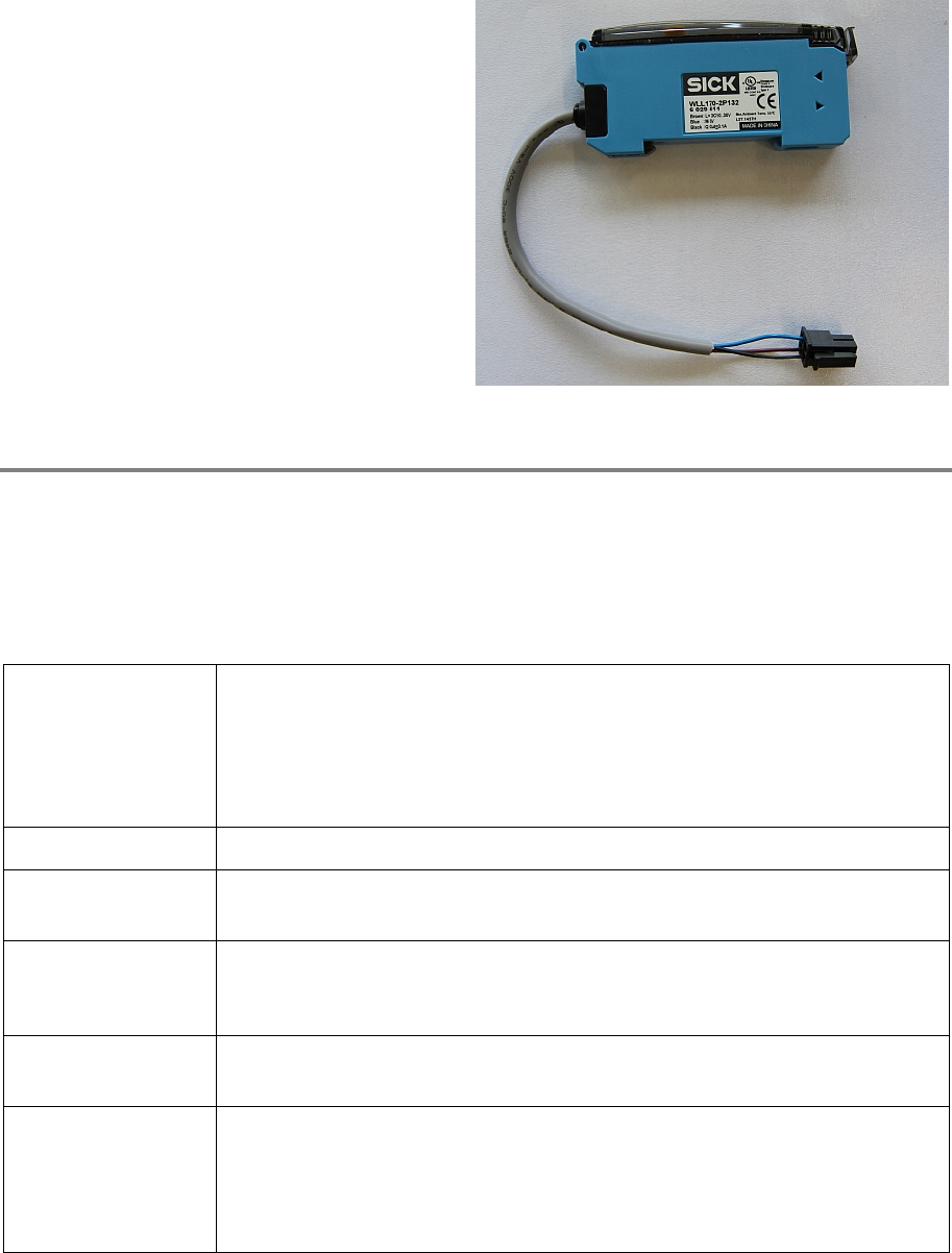
Spare parts:
0312454
8-01, Optosensor LL3_DE02
Time needed
Schedule around 10 minutes for this task.
7.8.3 Prerequisites
For a safe and efficient maintenance, the following prerequisites have to be fulfilled:
Personnel:
• Any work with or at the equipment must be carried out by skilled and
trained personnel in accordance with the locally applicable
regulations.
• Inform all involved persons regarding the currently running
maintenance works.
Machine loading:
• Stored items do not have to be unloaded.
Machine operating
condition:
• Shut down
Main electrical
power:
• Equipment disconnected from power supply system. The Main Switch
(switched off) locked by means of a padlock to secure the main switch
against unintentional switching on.
Compressed air /
Nitrogen (if used):
• Equipment disconnected from nitrogen.
Access:
• Open the door on the right side of the machine
• Pull the Z axis towards you
• Pull the gripper up (is a bit hard because the Z motor has a break) so
you have better access to the gripper
Gripper 00197973-10 / 02 , 2016
7-44 © ASM SIPLACE Mat. Tower Storage Service Manual
7.8.4 Exchange and setup steps
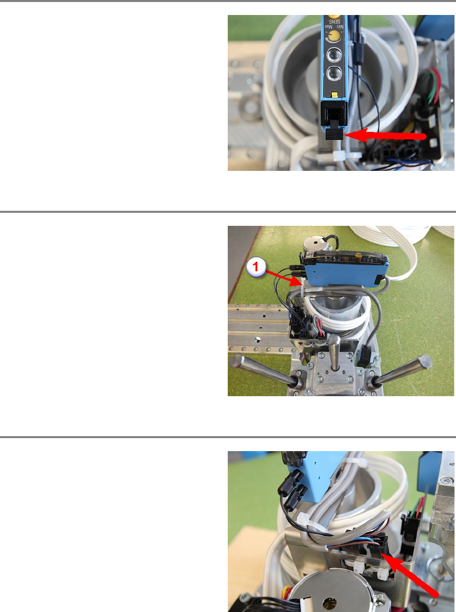
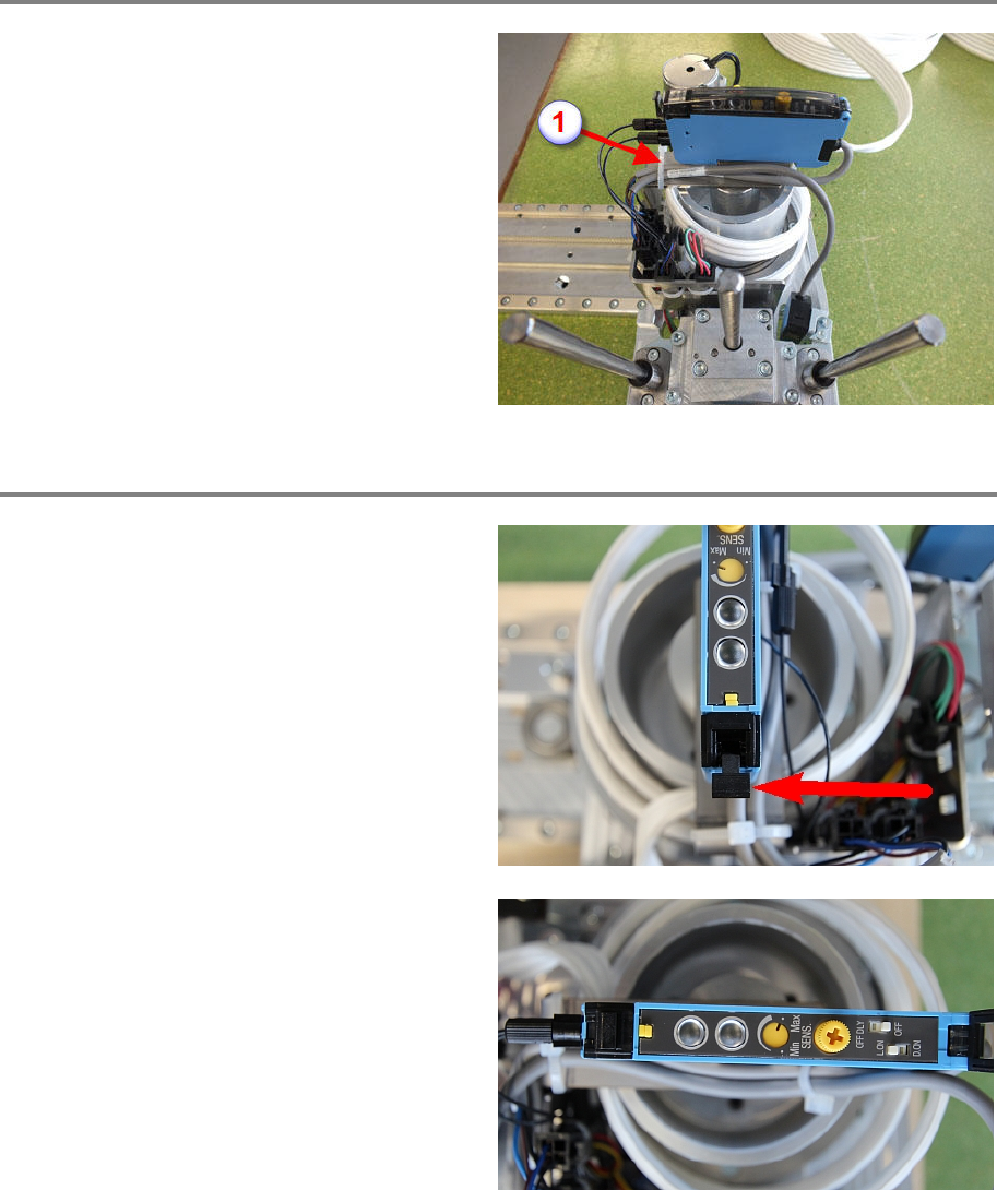
Step 1
Open the sensor cover.
P
ush down the clip marked in the picture. Now
both connectors with the fibre
-optic cables can
be pulled out.
Step 2
Cut the cable tie (1) marked on the photo.
Cut also the cable tie (2) if existing.
Step 3
Disconnect the sensor cable. Check if the
marked
connector in the picture is the correct
one, as they can be mixed.
Now the sensor can be removed by pulling up
on the rear side.
Fit the new sensor and reconnect the sensor
cable.
00197973-10 / 02 , 2016 Gripper
SIPLACE Mat. Tower Storage Service Manual © ASM 7-45
Step 4
Reconnect the sensor cable and apply the cable
tie (1). Take care that the direction of the cable is
similar as shown in the picture.
Do not apply the second cable tie (2), the cable
of the H sensor will be d
amaged.
Step 5
Push in both fibre
-optic connectors and pull up
the clip marked in the picture to fixate them.
Check the sensor configuration is similar as
shown in the picture.