00197973-10_SM_MaterialTower.pdf - 第220页
Option Air Dryer 0019797 3 - 10 / 02 , 2016 11-6 © ASM SIPLACE Mat. Tower St ora ge Ser vice Man ual Step 3 The air dryer is mounted above the el ectronics. No exact po sition is requi red. Let approx imately 300 mm dist…
00197973-10 / 02 , 2016 Option Air Dryer
SIPLACE Mat. Tower Storage Service Manual © ASM 11-5
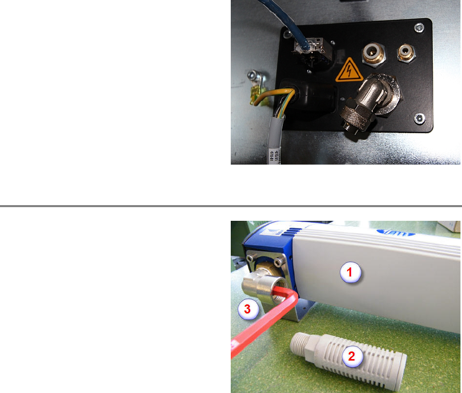
Built in all bulkhead unions as shown on the
picture.
The silencer is mounted into the outer side of
the 15mm bulkhead union.
The 4mm outer connection stays empty.
The orientation of the elbow union must be as
shown on the picture.
Step 2
Before mounting the air dryer (1), to meet the
production requirement, remove or add the Air
Flow Limiter.
Remove the silencer (2)
By using the Allen ke
y loosen and remove or
screw in and tighten the Air Flow Limiter (3)
Re
-mount the silencer (2)
Option Air Dryer 00197973-10 / 02 , 2016
11-6 © ASM SIPLACE Mat. Tower Storage Service Manual
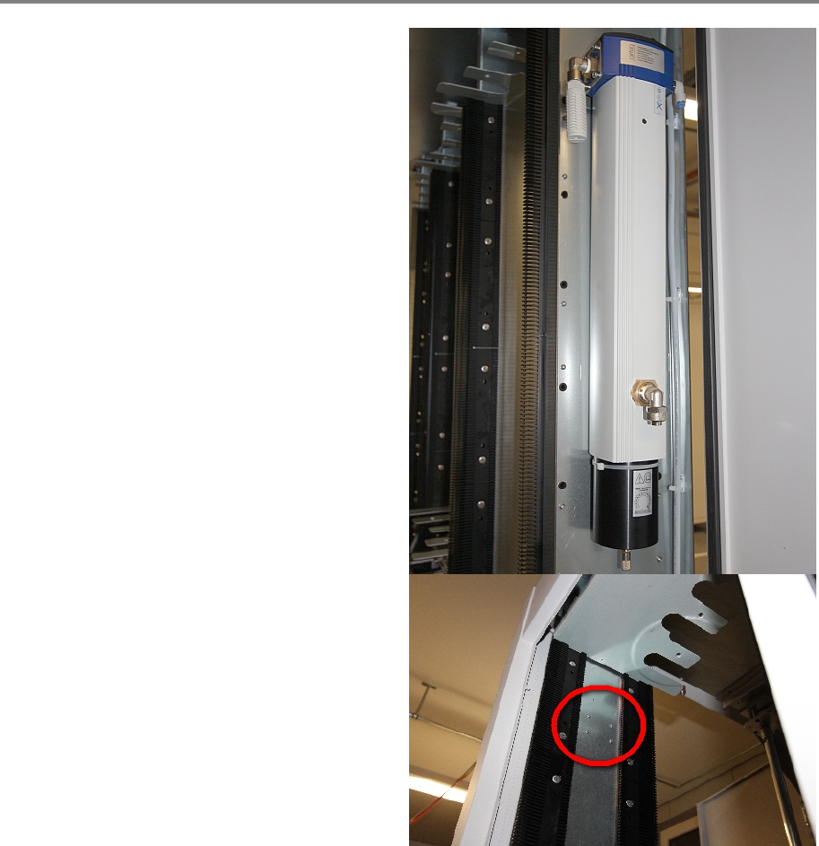
Step 3
The air dryer is mounted above the electronics.
No exact position is required. Let approximately
300 mm distance between the air dryer and the
beginning of the plate.
If there are no holes prepared on the electric
plate, drill the holes with 4mm diameter
according to the holes in the holding plate. Of
the air dryer.
Fit the air dryer by screwing in the screws from
the back side.
00197973-10 / 02 , 2016 Option Air Dryer
SIPLACE Mat. Tower Storage Service Manual © ASM 11-7
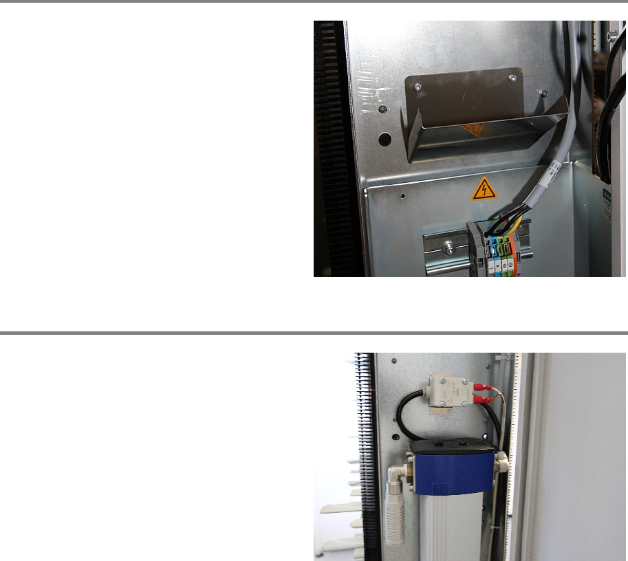
Step 4
Mount the drain cover below the air dryer. No
exact position is required.
If no holes are prepared. Drill 2.5mm holes and
use a 3mm th
read cutter.
ATTENTION: Make sure the screws are not
too long. At the back side they must not
overlap 2mm
Step 5
Mount the magnetic valve abo
ve the air dryer.
No exact position is required.
If no holes are prepared. Drill 2.5mm holes and
use a 3mm thread cutter.
ATTENTION: Make sure the screws are not
too long. At the back side they mustn't
overlap 2mm