00197973-10_SM_MaterialTower.pdf - 第252页
Serv ice D oor Monit oring 0019797 3 - 10 / 02 , 2016 12 -6 © ASM SIPLACE Mat. Tower St ora ge Ser vice Manu al On the right s ide of the ma chine, mount an edge protector on top bet ween reinforcing bra cket and stack (…
00197973-10 / 02 , 2016 Service Door Monitoring
SIPLACE Mat. Tower Storage Service Manual © ASM 12-5
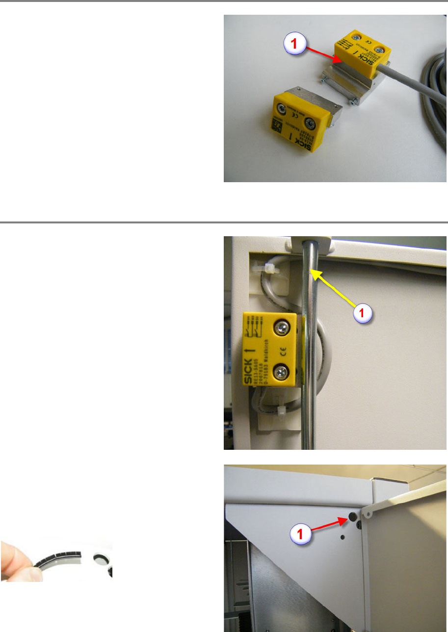
Preparation of sensors
Fix both sensors and both magnets to the
support plates, shown on the picture.
The sensor fixation has slotted
holes for
adjusting the sensor. For the preparation the
sensor should be flush with the edge of the
support plate (1).
Preparation for cabling
On both sides of the machine, the sensor switch
(the part with the cable) is mounted on the door
with the locking mechanism (1), see picture.
On the left and the right side of the machine, the
hole (1) of the reinforcing bracket (diameter 15
mm) will be used as cable bushing (at the doors
with locking mechanism). To protect the cable a
grommet has to be mounted.
Mount the grommets on the holes on both sides
of the machine (see picture).
Service Door Monitoring 00197973-10 / 02 , 2016
12-6 © ASM SIPLACE Mat. Tower Storage Service Manual
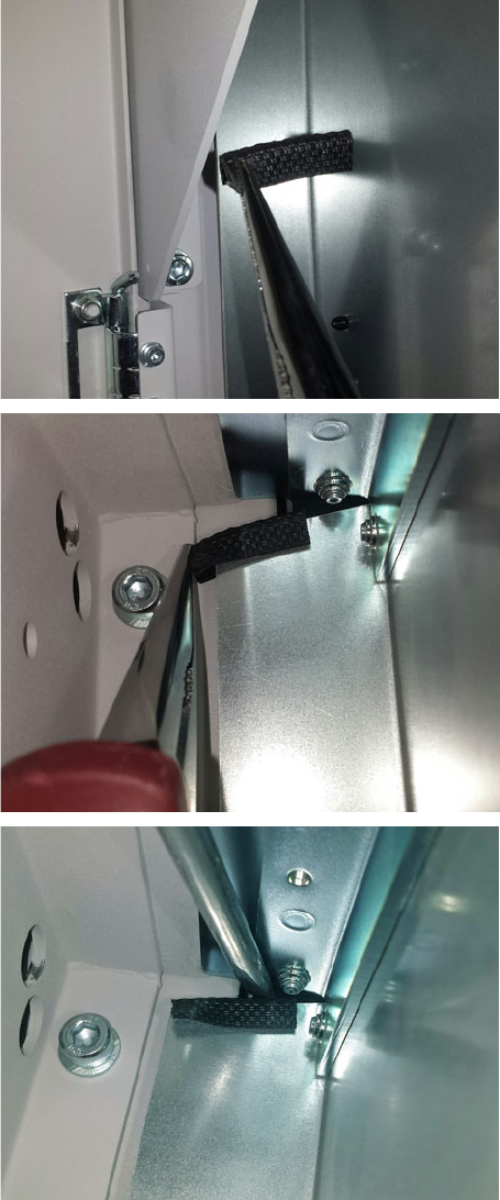
On the right side of the machine, mount an edge
protector on top between reinforcing bracket
and stack (see picture series). It is the aim to
protect the sensor cable. The blank edge of the
sheet metal would scrub
at the cable as a result
of door opening and closing and possible
vibrations.
Grasp the edge protector by means of a long
-
nose plier.
Slide the edge protector over the edge of the
sheet metal.
At the end, press the edge protector down by
using a screw
driver.
On the left side of the machine, if not already
exist, mount an edge protector on the side of
the sheet metal where the existing cables are.
Scrubbing on the left side is not that critical, but
to prevent any malfunction it is recommended
to mount
the protector.
00197973-10 / 02 , 2016 Service Door Monitoring
SIPLACE Mat. Tower Storage Service Manual © ASM 12-7
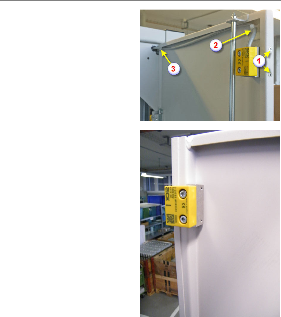
Mounting Sensor and Magnet, left side of the machine
Fix the sensor (part with the 3050 mm cable) on
the left side of the machine, on the door with
the locking mechanism.
Tighten the screws and make sure again the
screws are flush with the door surface (1).
Attach an adhesive pad (2) on top of the sensor.
Route the cable as shown on picture, fix it with a
cable tie and route it through the hole of the
door (3).
Fix the magnet (part without cable) on the
opposite door without locking mechanism.
Tighten the screws and make sure again the
screws are flush with the door surface.