OM-1241-005_w.pdf - 第161页
5-B AIX-ML T-ID 0705-003

5-A
AIX-MLT-ID
0705-003
Chapter 5
Supplement
This chapter describes the pneumatic diagrams, the
parts location, the location of sensors and loads, the
electrical circuit diagrams, etc.
As this chapter contains highly sophisticated contents, it
should carefully be referred to.
•
Pneumatic Diagram
• Layout of Sensors and Loads
• Parts Location
• Electrical Circuit Diagrams

5-B
AIX-MLT-ID
0705-003
5-1
AIX-MLT-ID
0705-003 -(M806XER--0001)
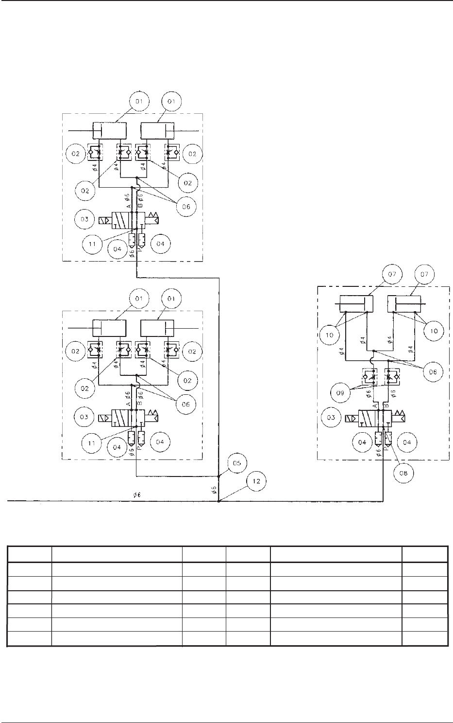
1. Pneumatic Diagram
1.1 Pneumatic Diagram (FP-G100R) and (FP-G100L)
Traverse Unit
Pallet Chuck
Elevator Axis 2 (Upper)
Rack Shutter (Upper)
Elevator Axis 1 (Lower)
Rack Shutter (Lower)
From the manifold (KM13-08-10-3) of the main machine (GX)
Symbol Name Q'ty
Symbol Name Q'ty
01 Cylinder 4
02 Speed Controller 8
03 Solenoid Valve 3
04 Silencer 6
05 Half Union 2
06 Different Union Y 6
07 Cylinder 2
08 Elbow Union 1
09 Speed Controller 2
10 Half Elbow 4
11 Half Union 2
12 Union Y 1
1. Pneumatic Diagram