OM-1241-005_w.pdf - 第48页
1-11 AIX-ML T-P Rack Shutter Rack Shutter MG-G1 10 MG-G1 15 Magazine Door Magazine Door Fig. A3 Magazine Pallet (MP-G100) T ray Magnet (MF-G100) Fig. A4 Pallet and T ray Magnet 0705-003 3. Name of Each Section and Handli…
1-10
AIX-MLT-P
3. Name of Each Section and Handling
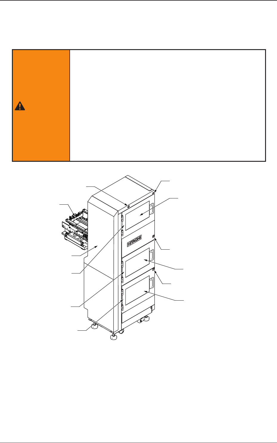
This feeder is constructed of an elevator, magazines, a traverse, pallets, and
tray magnets.
WARNING
There are strong motorized and high-voltage areas inside the
machine. Special caution should be paid not to touch them.
Doing otherwise will cause personal injury (serious accident).
·
Onlyqualiedmaintenancepersonnel
shoulddetach
the covers.
·
The machine should be operated with the covers
being attached.
·
If a cover is detached, be sure to reattach it.
·
Be sure to close the magazine door before operating
the machine.
·
Do not disengage the interlock of the magazine door.
Elevator
Elevator Power LED
Magazine #2 Supply Position
Upper Magazine
Change Position
Magazine Change Position
Magazine #1 Supply Position
Lower Magazine
Change Position
Traverse
Magazine #2 Door
Exchange Position Door
Magazine #1 Door
Magazine #2 Ready Switch
Exchange Position
Ready Switch
Magazine #1 Ready Switch
Fig. A1 Multi-Layer Tray Feeder (Front Side of Machine)
0705-003
3. Name of Each Section and Handling
1-11
AIX-MLT-P
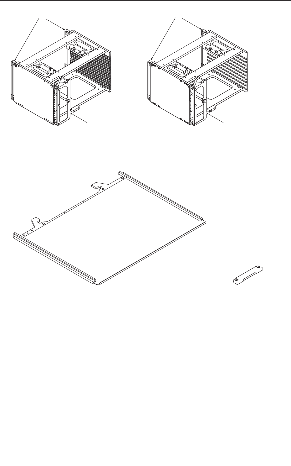
Rack Shutter
Rack Shutter
MG-G110MG-G115
Magazine Door Magazine Door
Fig. A3 Magazine
Pallet (MP-G100)
Tray Magnet
(MF-G100)
Fig. A4 Pallet and Tray Magnet
0705-003
3. Name of Each Section and Handling
1-12
AIX-MLT-P
3.1 Elevator
The elevator is provided with a mechanism that moves the magazines up and
down.
The elevator can be loaded with two magazines in which the pallets are
stored. Each magazine is driven up and down separately.
The trays on the pallets in each magazine can be replenished with
components or the trays on each pallet can be reloaded with components at
the specied position.
The magazines can manually be attached to or detached from the elevator.
The magazine loaded on the elevator is clamped with a spring force and
positioned in place.
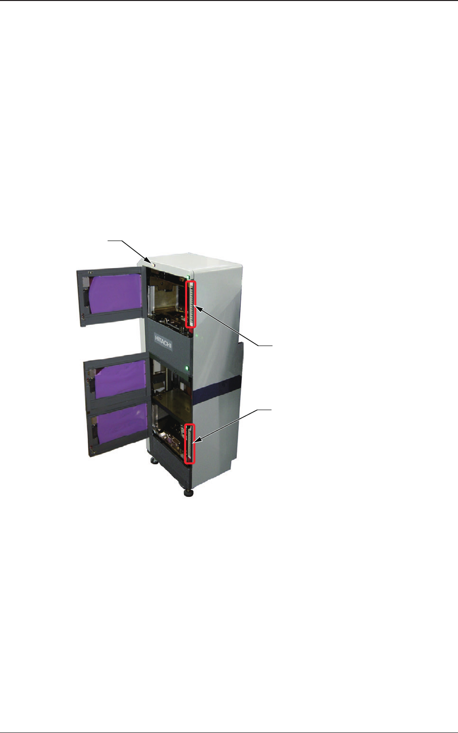
Lower [ALL CHANGE] Button and
Stage No. Buttons ([1] through [15])
Elevator Power LED
Upper [ALL CHANGE] Button and
Stage No. Buttons ([1] through [15])
Fig. A5
(1) Elevator Power LED
This LED indicates whether or not the elevator is powered.
When the elevator is powered, the LED illuminates.
0705-003
3.1 Elevator