OM-1241-005_w.pdf - 第49页
1-12 AIX-ML T-P 3.1 Elevator The elevator is provided with a mechanism that moves the magazines up and down. The elevator can be loaded with two magazines in which the pallets are stored. Each magazine is driven up and d…
1-11
AIX-MLT-P
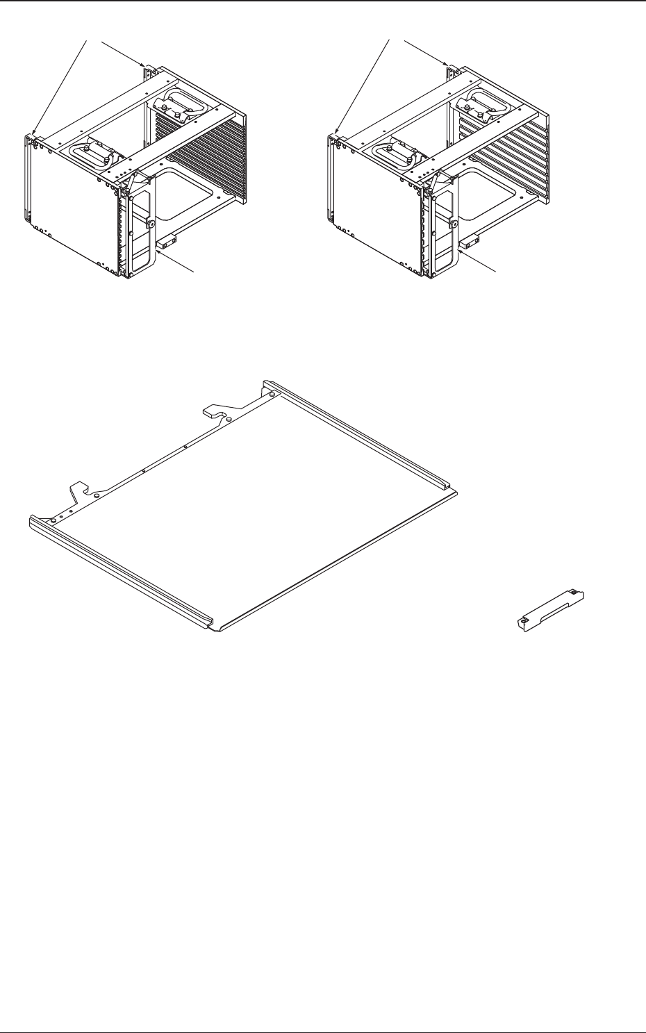
Rack Shutter
Rack Shutter
MG-G110MG-G115
Magazine Door Magazine Door
Fig. A3 Magazine
Pallet (MP-G100)
Tray Magnet
(MF-G100)
Fig. A4 Pallet and Tray Magnet
0705-003
3. Name of Each Section and Handling
1-12
AIX-MLT-P
3.1 Elevator
The elevator is provided with a mechanism that moves the magazines up and
down.
The elevator can be loaded with two magazines in which the pallets are
stored. Each magazine is driven up and down separately.
The trays on the pallets in each magazine can be replenished with
components or the trays on each pallet can be reloaded with components at
the specied position.
The magazines can manually be attached to or detached from the elevator.
The magazine loaded on the elevator is clamped with a spring force and
positioned in place.
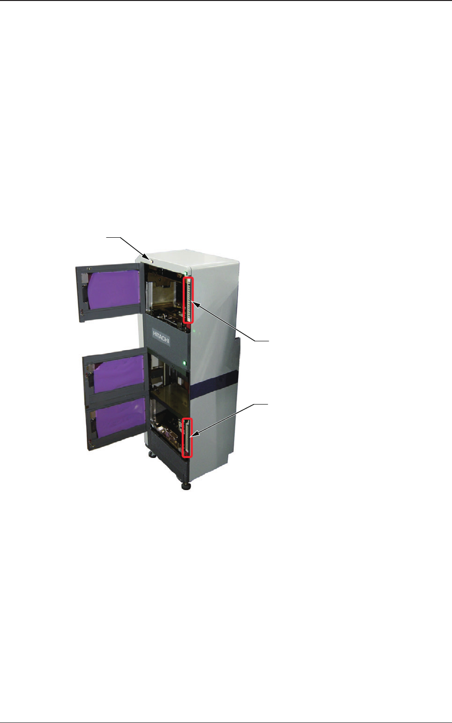
Lower [ALL CHANGE] Button and
Stage No. Buttons ([1] through [15])
Elevator Power LED
Upper [ALL CHANGE] Button and
Stage No. Buttons ([1] through [15])
Fig. A5
(1) Elevator Power LED
This LED indicates whether or not the elevator is powered.
When the elevator is powered, the LED illuminates.
0705-003
3.1 Elevator

1-13
AIX-MLT-P
(2) Ready Switches
(Magazine #1 Ready, Exchange Position Ready, Magazine #2 Ready
Switches)
The machine is equipped with doors and ready switches ("Magazine #1",
"Exchange Position", and "Magazine #2") at each individual magazine
exchange and component supply positions.
The LED of each ready switch indicates the following.
•
When the LED illuminates in green, it indicates that the door is
electromagnetically locked, making it impossible to be opened.
•
When the LED is ickering in green, it indicates that the magazine is
moving toward the change position.
•
When the LED is turned off, it indicates that the door is not locked
and can be opened.
(3) Stage No. Buttons [1] through [15] and [ALL CHANGE] Button
Provided on the inner sides of Magazine #1 and #2 Doors are Stage No.
buttons ([1] through [15]) and the [ALL CHANGE] buttons. Each Stage No.
can be referred to for checking if a tray is inserted or not.
•
When the LED illuminates in green, it indicates that the stage of the
corresponding No. is loaded with components.
•
When the LED is ickering in green, it indicates that the stage of the
corresponding No. is short of components.
•
When the LED is turned off, it indicates that no stage data is specied
in the pattern program.
When the stage in a component shortage error (ickering LED of the stage
No. button) is reloaded with components and the corresponding stage No.
button is pressed, the LED illuminates in green.
When several stages in component shortage errors are reloaded with
components and the [ALL CHANGE] button is pressed, the LEDs of the
corresponding stage Nos. are turned on.
Note
When MG-G110 is used, Stage No. Buttons ([11] through [15]) will not be
used.
The lamps of Stage No. Buttons [11] through [15] are always turned OFF.
3.1 Elevator
0705-003