OM-1241-005_w.pdf - 第80页
2-16-1 AIX-ML T-ID [1] Unit Selection Buttons These buttons can be used to specify the feeder base whose carrier data should be conrmed or changed. [2] Information Display Displayed is the component carriage data of the…
2-16
AIX-MLT-ID
[1] [2]
[3] [4]
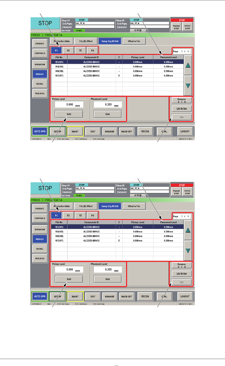
Fig. B10 "Comp Crg Dt Edit" Window (3/4)
[1] [2]
[3] [4]
Fig. B10-1 "Comp Crg Dt Edit" Window (4/4)
0804-004
2.4 Production Data

2-16-1
AIX-MLT-ID
[1] Unit Selection Buttons
These buttons can be used to specify the feeder base whose carrier data
should be conrmed or changed.
[2] Information Display
Displayed is the component carriage data of the feeder base (the multi-
layer tray feeder) selected in [1].
[3] Mode Buttons
These buttons are used to change the direction of component feed,
the auto feeder axis adjustment X and Y, the pickup level, and the
placement level.
[4]
[Screens #/3], [Lib Dt Set], and [Set] Buttons
[Screens #/3] Button :
T
his
button can be used to open another page.
[Lid Dt Set] Button :
When pressed, this button resets the selected
component data to the defaults registered in
the component library.
[Set] Button :
When pressed, this button sets the changed
contents.
2.4 Production Data
0804-001
2-17
AIX-MLT-ID
3. Menus for Maintenance
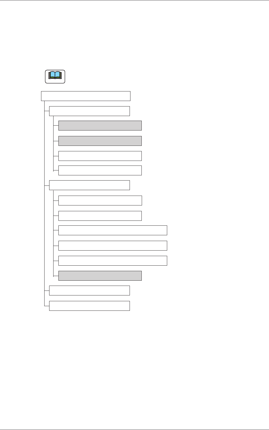
3.1 Outline of Menus for Maintenance
The following shows the hierarchical structure of the menus (including the
submenus and windows) for the maintenance operation.
Note
The shadowed (gray) items are related to the multi-layer tray feeder.
Menus for Maintenance Reference Item Nos.
Device Check
Input/Output 3.2.1
Motor 3.2.2
Recognition
Program Information
Unit Adjustment
Linear Measure
Nozzle Change
Feeder Base & Feeder Connection
Cutting Adjustment
Conveyor PCB Stopper
Tray Unit 3.3.1
Device Test
Teaching
Fig. B11 Outline of Menus for Maintenance
0705-003
3. Menus for Maintenance