00198500-02_VD_711.1_R18-1_DE_EN - 第17页
Station Software 71 1.1 (R18 - 1) / Versio n Description 05/2018 Edition 17 5 Features o f the 71 1.0 Station Software Ver sion All features of t he previous 7xx stati on software versions ar e also supported in t he 71 …
Station Software 711.1 (R18-1) / Version Description 05/2018 Edition
16
The dies to be measured from a wafer must be selected in SIPLACE Pro. Each die that shall be
measured by the Front-Back-Offset Measurement must be enabled. The dies which are used for
Front-Back-Offset Measurement will be picked-up at first and used to compute the offset average.
The resulting offset is used for all other dies of this wafer to place the dies correctly.
An individual wafer can be selected in the Setup view of the SIPLACE Wafer System on the station
software GUI. If Front-Back-Offset Measurement is activated for dies provided by this wafer, the
following specific data will be displayed for the wafer:
– Offset and deviation
– Number of measured dies
– Number of measured dies with a minimum percentage of measured dies with "good result". I.e.,
the measurement was successful and the measurement result was used to compute the offset.
All component shapes must be complete before production starts. Teaching during production is
not supported.
4.11 Checking GigE Camera Connections – Enhanced Functionality
The functionality to check GigE camera connections has been enhanced in the Maintenance view
under Camera Verification – Check all camera connections. In addition to failed connections, a
possibly existing transmission error rate for working connections will be displayed.
The transmission error rate is displayed in DPM (Defects Per Million).
1 DPM = from one million transmitted data packages, one package was faulty.
A transmission error rate < 10 DPM is no problem but significantly higher values indicate a
hardware problem of the transmission link. In this case, the plug of the trailing cable should be
checked. Possibly, the VBI (Vision Base Interface) and / or VHI (Vision Head Interface) have to be
exchanged.
Station Software 711.1 (R18-1) / Version Description 05/2018 Edition
17
5 Features of the 711.0 Station Software Version
All features of the previous 7xx station software versions are also supported in the 711.0 station
software version. The main new features of the 711.0 station software version are listed below.
NOTICE
Detailed information on the individual functions can be found in the Online help for the
station software.
5.1 "The Hermes Standard" – New Communication Protocol
Compatible mode: Partly compatible
"The Hermes Standard" is a new communication protocol for SMT assembly lines that can be used
alternatively to the electrical SIPLACE SMEMA interface. With this protocol, more information can
be transferred with the board down the line like unique board Ids, barcodes, conveyor speed, board
length / width / thickness. All this information can be transferred down the complete line, without
any interruption. Up to now, this was only possible within a SIPLACE SMEMA cluster. If all devices
in the line support "The Hermes Standard", whispering down the line is possible within "The
Hermes Standard" cluster as it is within the SIPLACE SMEMA cluster.
"The Hermes Standard" is supported on the X-series S, TX-series and TX micron-series placement
machines.
The sequence of machines and devices (SIPLACE, ASYS, others) has to be configured in
SIPLACE Pro so that every machine / device in the production chain knows about its next and
previous device per transport lane including their according IP-addresses.
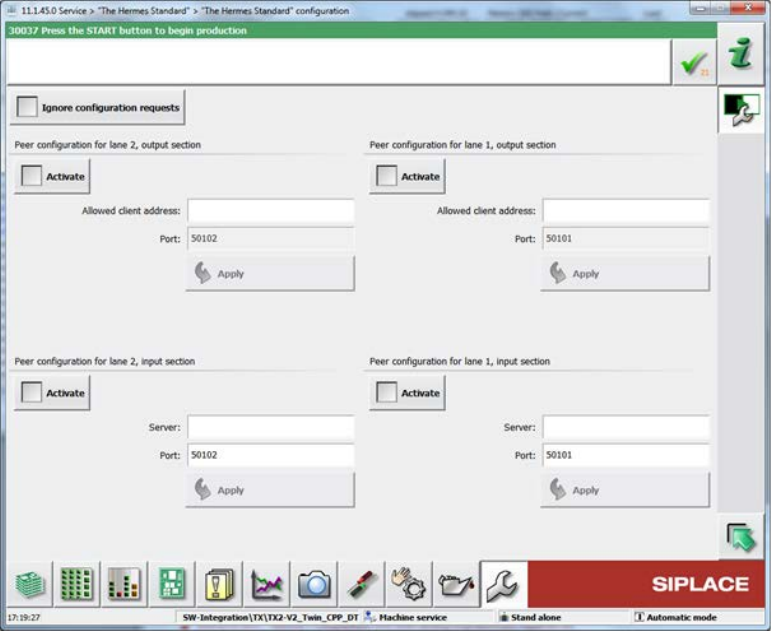
The hardware options (activate peer, host, IP address) related to "The Hermes Standard" can be
configured on the station software GUI in the "The Hermes Standard" configuration dialog under
Service – Configure machine – "The Hermes Standard".
Station Software 711.1 (R18-1) / Version Description 05/2018 Edition
18
Figure 5-1: "The Hermes Standard" configuration dialog
For diagnostic purposes, a view has been added to the Event tool. For each "The Hermes
Standard" end-point, a tab page is displayed, listing the received and sent messages. Only the last
100 messages after the GUI started are displayed.
If all devices between the first and the last SIPLACE station use "The Hermes Standard",
whispering of the station-wise download is supported even if 3
rd
-party equipment is setup in
between the SIPLACE devices. The user only has to confirm the changeover at the first SIPLACE
station but no longer at the SIPLACE station after the AOI system.
Restrictions
– No support for stations with shuttle.
– No support for devices with IPv6 addresses.
5.2 New Placement Force – Very Low Force in Placement, Pickup and
Dipping Processes
Compatible mode: Hidden
The new very low placement force (0.5 N) for pickup, placement and dipping is supported by the
station software. The very low force state has to be set in SIPLACE Pro and can be enabled for the
following placement heads: C&P20 M2, C&P20 P and (from R18-1) C&P20 P2.
All segments of the concerned placement heads will be measured when the first board enters the
machine to check which segments are able to handle this hardware requirement. The results are
displayed in the new Very low force column of the list in which the height values of the nozzles are
displayed (Manual Operations – Subsystems – Gantry n –x Head – Segments – Height
values).
Additionally, the measurement can be performed in the Maintenance view under Test bench
inspection with the measurement step Z axis movement.