Siplace TX-设备参数-EN - 第10页
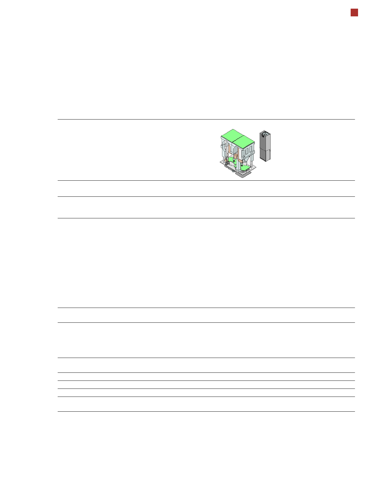
10 Placement heads SIPLACE MultiStar (CPP) SIPLACE MultiStar (CPP) with component came ra type 30 With component camera type 45 with component camera type 33 (stationary camera) Component range a a) Please note that the …
9
Placement heads
SIPLACE SpeedStar (C&P20 P)
SIPLACE SpeedStar (C&P20 P)
With component camera
type 23
With component camera
type 41
Component range
a
a) Please note that the placeable component range is also affected by the pad geometry, the customer-spe-
cific standards, the component packaging tolerances and the component tolerances.
01005 to 2220, Melf, SOT,
SOD
0201 (metric) to 2220, Melf,
SOT, SOD, Bare-Die, Flip-
Chip
Component spec.
Max. height
Min. lead pitch
Min. lead width
Min. ball pitch
Min. ball diameter
Min. dimensions
Max. dimensions
Max. weight
4 mm
0.25 mm
0.1 mm
0.4 mm
0.2 mm
0.18 mm x 0.18 mm
6 mm x 6 mm
1 g
4 mm
0.08 mm
0.03 mm
0.10 mm
0.05 mm
0.12 mm x 0.12 mm
6 mm x 6 mm
1 g
Programmable set-down
force
1.3 - 4.5 N 1.3 - 4.5 N
Nozzle types 40xx 40xx
X/Y accuracy
b
b) The accuracy values are measured during the machine acceptance tests. They correspond to the condi-
tions set out in the ASM scope of service and supply.
± 30µm / 3σ ± 30 µm/3σ
± 25 µm / 3σ with HPF
c
c) HPF = High Precision Flag
Angular accuracy ± 0.5° / 3σ ± 0.5° / 3σ
Illumination level 5 5
Standard functions High-resolution camera, vacuum sensor, force measurement, component
sensor, integrated turning station per segment, PCB warpage check, individ-
ual image of each component
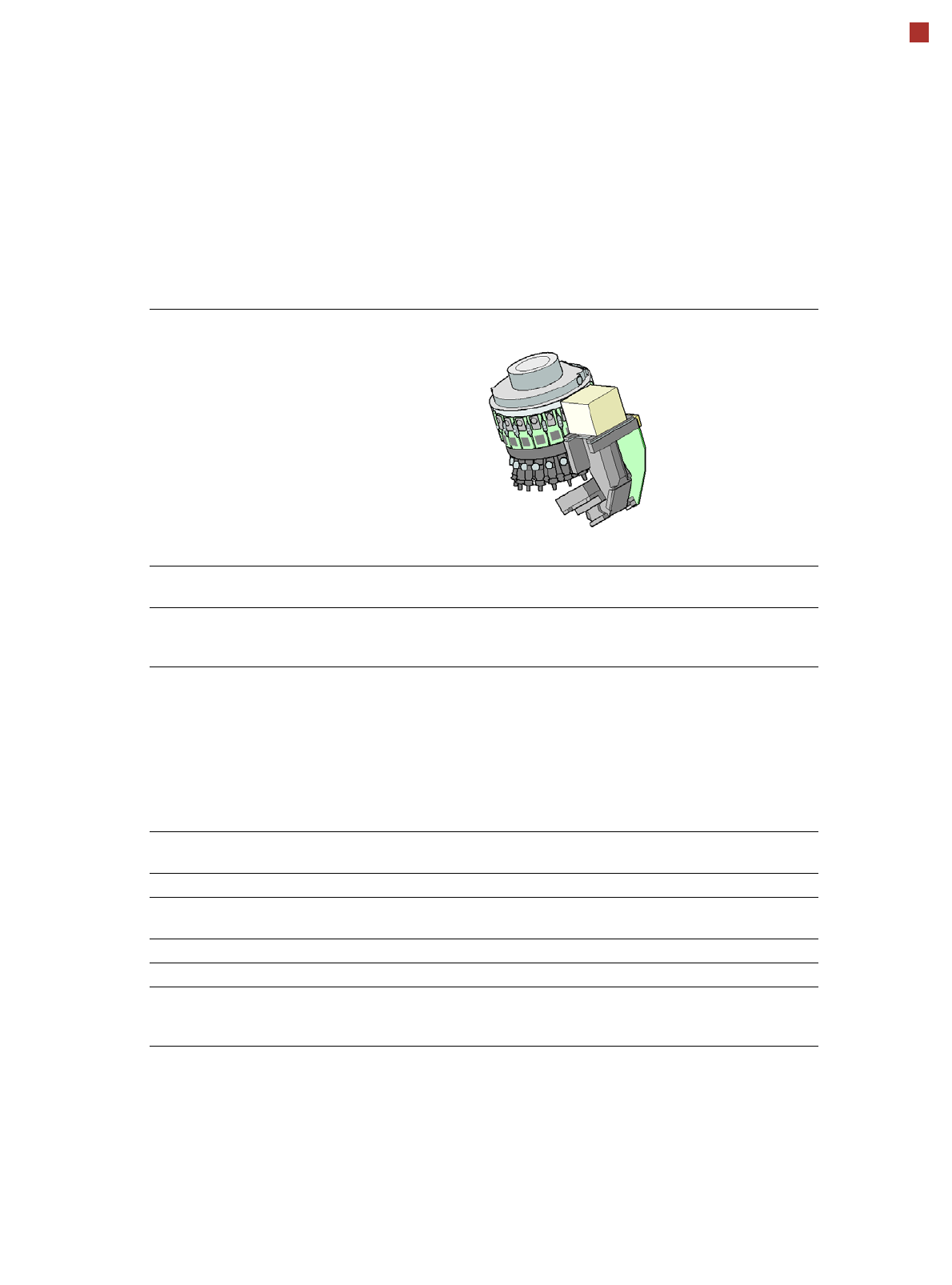
10
Placement heads
SIPLACE MultiStar (CPP)
SIPLACE MultiStar (CPP)
with component camera
type 30
With component camera
type 45
with component camera
type 33
(stationary camera)
Component range
a
a) Please note that the placeable component range is also affected by the pad geometry, the customer-specific stan-
dards, the component packaging tolerances and the component tolerances.
01005 to 27 mm x 27 mm 01005 to 15 mm x 15 mm 0402 to 50 mm x 40 mm
b
b) A diagonal of 69 mm is possible during multiple measurements (e.g. 64 mm x 10 mm).
Component spec.
Max height
c
Max. height
d
Min. lead pitch
Min. lead width
Min. ball pitch
Min. ball diameter
Min. dimensions
Max. dimensions
Max. weight
c) CPP head: in low installation position (stationary component camera not possible).
d) CPP head: in high installation position
6.0 mm
8.5 mm
0.25 mm
0.10 mm
e
/ 0.2 mm
f
0.25 mm
e
/ 0.35 mm
f
0.14 mm
e
/ 0.20 mm
f
0.4 mm x 0.2 mm
27 mm x 27 mm
4 g
e) For components < 18 mm x 18 mm
f) For components ≥ 18 mm x18 mm
6.0 mm
8.5 mm
0.25 mm / 0.12 mm
g
0.05 mm
0.14 mm
0.07 mm
0.11 mm x 0.11 mm
15 mm x 15 mm
4 g
g) Only possible for components which are within the camera focal area of ± 1.3 mm.
11.5 mm
0.3 mm
0.15 mm
0.35 mm
0.2 mm
1.0mm x 0.5mm
50 mm x 40 mm
8 g
Programmable set-down
force
1.0 - 10 N 1.0 - 10 N 1.0 - 10 N
Nozzle types 20xx, 28xx 20xx, 28xx 20xx, 28xx
X/Y accuracy
h
h) The accuracy values are measured during the machine acceptance tests. They correspond to the conditions set
out in the ASM scope of service and supply.
± 40 µm/3σ ± 40 µm/3σ ± 34 µm/3σ
Angular accuracy ± 0.20° / 3σ
i
, ± 0.38° / 3σ
j
i) Component dimensions between 6 mm x 6 mm and 27 mm x 27 mm.
j) Component dimensions smaller than 6 mm x 6 mm.
± 0.18° / 3σ ± 0.14° / 3σ
Illumination level 5 5 6
Standard functions High-resolution camera, vacuum sensor, force measurement, component sensor,
integrated turning station per segment, PCB warpage check, individual image of
each component
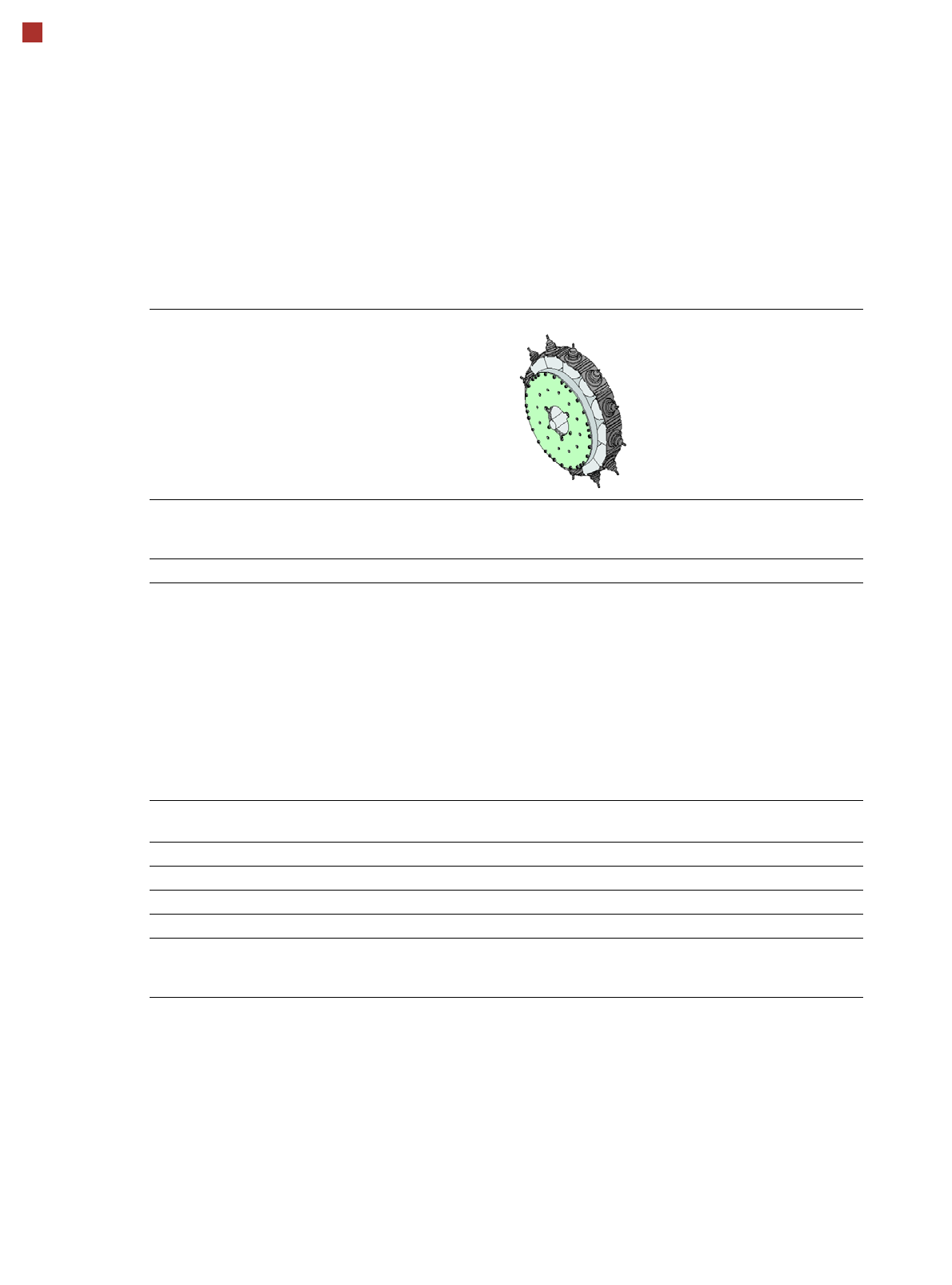
11
Placement heads
SIPLACE TwinStar (TH)
SIPLACE TwinStar (TH)
with component camera type 33
(fine pitch camera)
with component camera type 25
(flip chip camera)
Component range
a
a) Please note that the placeable component range is also affected by the pad geometry, the customer-specific standards, the
component packaging tolerances and the component tolerances.
0402 to SO, PLCC, QFP, BGA, special
components, bare dies, flip-chips
0201 to SO, PLCC, QFP, sockets,
plugs, BGA, special components, bare
dies, flip-chips, shields
Component specs
Max. height
Min. lead pitch
Min. lead width
Min. ball pitch
Min. ball diameter
Min. dimensions
Max. dimensions
Max. weight
b
b) Component plus nozzle or gripper.
25 mm
0.3 mm
0.15 mm
0.35 mm
0.2 mm
1.0mm x 0.5mm
55 mm x 45 mm (single measurement)
up to
200 mm x 125 mm (multiple measurement)
c
100 g
c) Further restrictions considered in SIPLACE Pro apply depending on component dimensions and component supply.
25 mm
0.25 mm
0.1 mm
0.14 mm
0.08 mm
0.6 mm x 0.3 mm
16 mm x 16 mm (single measurement)
100 g
Programmable set-down
force
1.0 N - 15 N 1.0 N - 15 N
Nozzle types 5xx (standard)
20xx/28xx + adapter
4xx + adapter
9xx + adapter
Gripper
5xx (standard)
20xx/28xx + adapter
4xx + adapter
9xx + adapter
Gripper
Nozzle spacing for P&P
heads
70.8 mm 70.8 mm
X/Y accuracy
d
d) The accuracy values are measured during the machine acceptance tests. They correspond to the conditions set out in the
ASM scope of service and supply.
± 28 µm/3σ ± 22 µm/3σ
Angular accuracy ± 0.05° / 3σ ± 0.05° / 3σ
Illumination level 6 6
Standard functions Stationary fine pitch camera, vacuum sensor, force measurement, nozzle changer,
PCB warpage check, individual image of each component