IM7585A987-02.pdf - 第12页
8 USB Settings and Connection 3 USB Setting Select the terminator setting. CR+LF CR 4 Press to conrm the setting. Connecting the USB Cable Connect a USB cable (commercially available USB cable) to the USB port of the in…
8
USB Settings and Connection
3
USB Setting
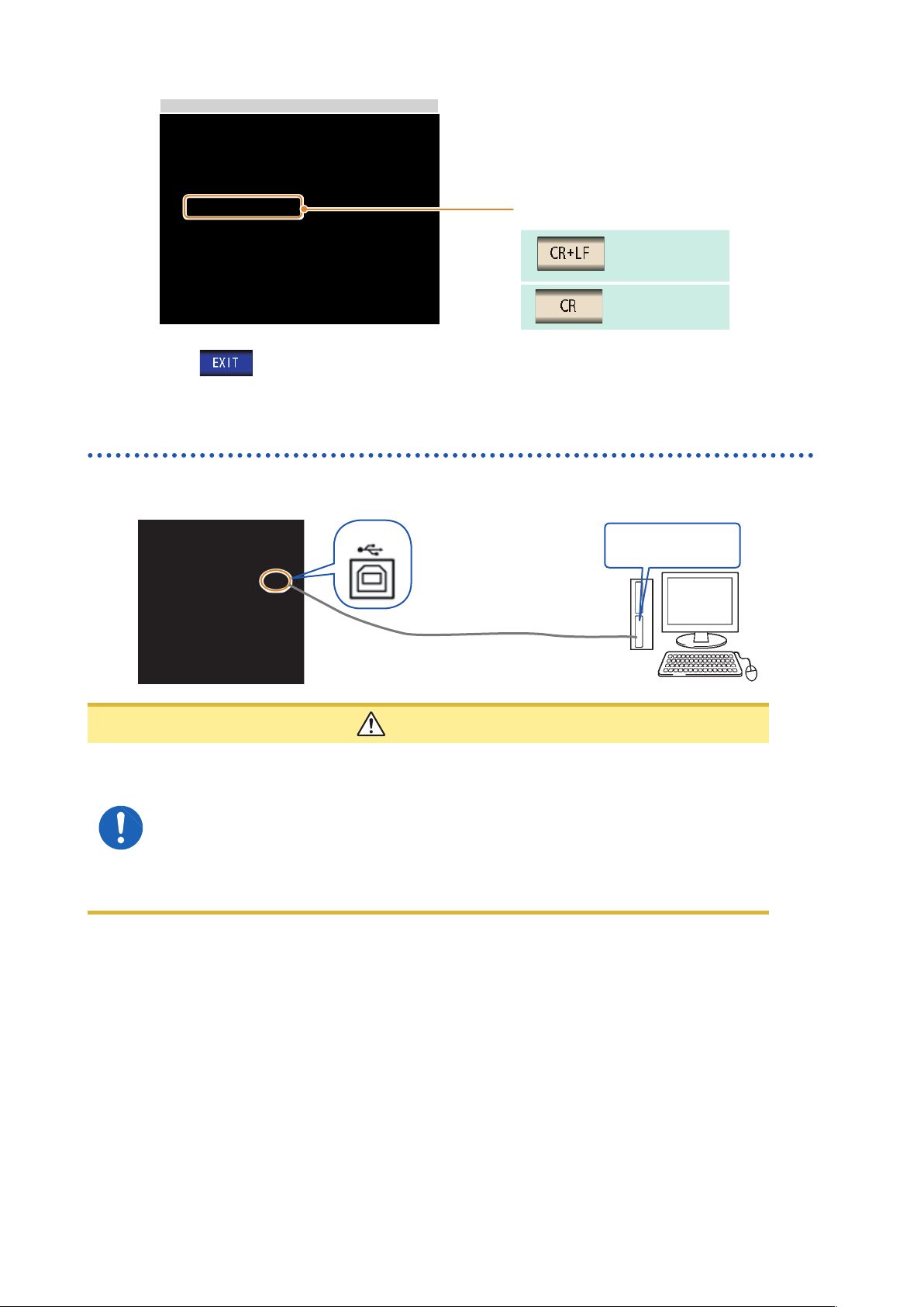
Select the terminator setting.
CR+LF
CR
4
Press to conrm the setting.
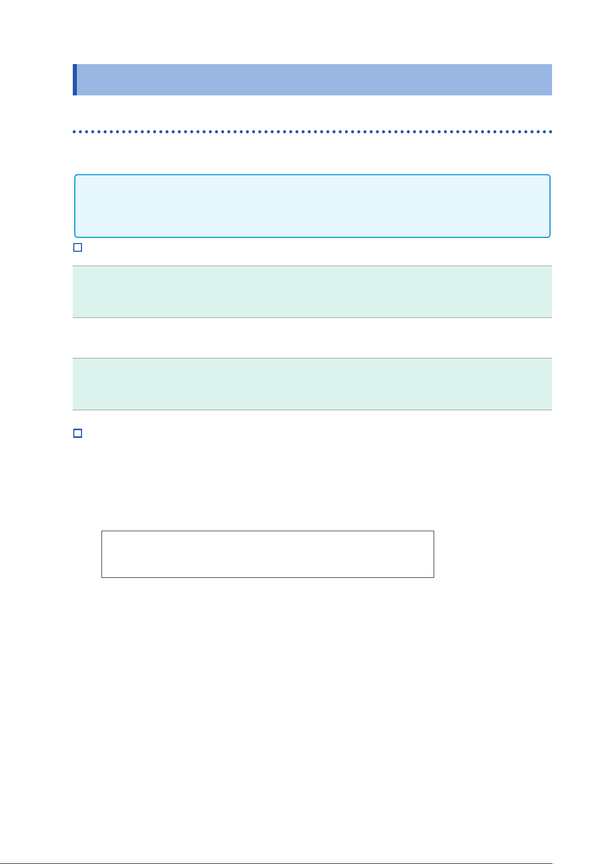
Connecting the USB Cable
Connect a USB cable (commercially available USB cable) to the USB port of the instrument.
USB cable (commercially
available product)
USB interface port of
computer
Type B
CAUTION
• To avoid faults
,
do not disconnect or reconnect the USB cable during instrument
operation.
• Connect the instrument and the computer to a common earth ground. Using different
grounds could result in potential difference between the instrument and the computer.
Potential difference on the USB cable can result in malfunctions and faults.
• Do not disconnect or connect other USB devices from or to
,
respectively
,
PC during
USB communications between instrument and computer. The USB communications
between instrument and PC may stop.
9
LAN Settings and Connection
2.3 LAN Settings and Connection
LAN Settings
You can perform command control using the TCP/IP protocol.
Set the instrument to match your network environment in advance.
• Make these settings before connecting to a network. Changing settings while connected can duplicate
IP addresses of other network devices
,
and incorrect address information may otherwise be presented
to the network.
• The instrument does not support DHCP (automatic IP address assignment) on a network.
Setting Items
IP address
Identies each device connected on a network.
Each network device must be set to a unique address.
The instrument supports IP version 4
,
with IP addresses indicated as four decimal octets
,
e.g.
,
“192.168.0.1”.
Subnet mask
This setting is for separating the IP address into the network address that indicates the
network and the host address that indicates the instrument. On this instrument
,
the subnet
mask is represented as four decimal numbers separated by “. “ such as “255.255.255.0.”
Default Gateway
When the computer and instrument are on different but overlapping networks (subnets)
,
this
IP address species the device to serve as the gateway between the networks.
If the computer and instrument are connected one-to-one
,
no gateway is used
,
and the
instrument’s default setting “0.0.0.0” can be kept as is.
Network Environment Conguration
Example 1. Connecting the instrument to an existing network
Example 1. Connecting the instrument to an existing network
When connecting the instrument to an existing network
,
the network settings need to be conrmed
in advance.
An IP address which is not the same as that of another network device needs to be assigned.
Conrm the following items with the network administrator
,
and write them down.
IP Address _________._________._________._________
Subnet Mask _________._________._________._________
Default Gateway _________._________._________._________
Example 2. Connecting multiple instruments to a single computer using a hub
When building a local network with no outside connection
,
the following private IP addresses are
recommended.
Example of private IP address:
IP Address.....................Computer: 192.168.0.100
Instrument: 192.168.0.1
,
192.168.0.2
,
192.168.0.3...
(Set an IP address that differs from that of other network devices.)
Subnet Mask..................255.255.255.0
Default Gateway.............OFF(0.0.0.0)...
Example 3. Connecting one instrument to a single computer using the 9642 LAN Cable
The 9642 LAN Cable can be used with its supplied connection adapter to connect one instrument
to one computer
,
in which case the IP address is freely settable. Use the recommended private IP
addresses.
IP Address.....................Computer: 192.168.0.100
Instrument: 192.168.0.1 (Set to a different IP address than the computer.)
Subnet Mask..................255.255.255.0
Default Gateway....OFF(0.0.0.0)
2