IM7585A987-02.pdf - 第19页
14 GP-IB Connection and Settings (when the Z3000 is connected) 2.4 GP-IB Connection and Settings (when the Z3000 is connected) Connecting the GP-IB Cable Connect the GP-IB cable to the GP-IB connector . Recommended cable…
14
GP-IB Connection and Settings (when the Z3000 is connected)
2.4 GP-IB Connection and Settings
(when the Z3000 is connected)
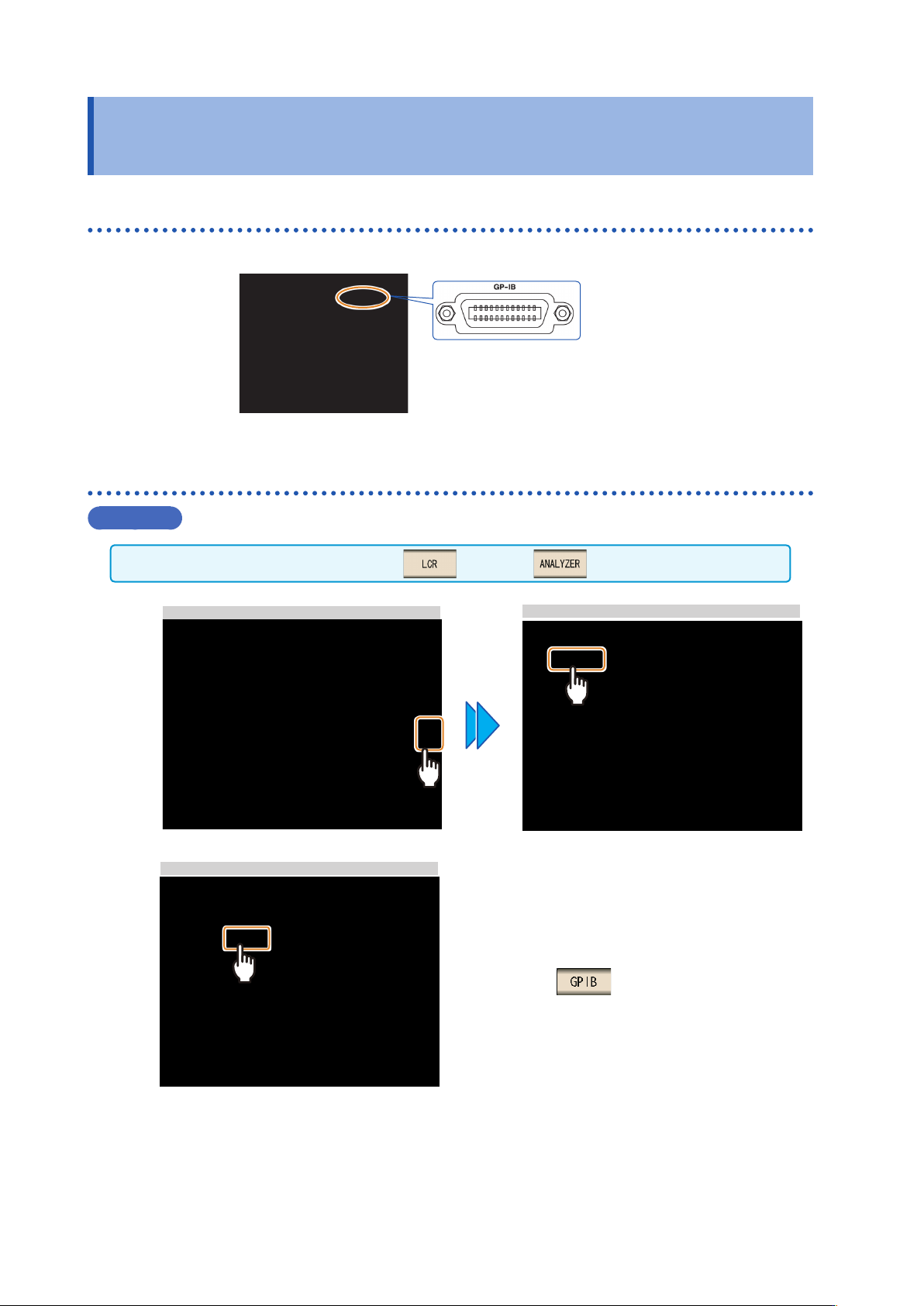
Connecting the GP-IB Cable
Connect the GP-IB cable to the GP-IB connector.
Recommended cable:
9150-02 GP-IB connection cable (2 m)
Setting GP-IB
Procedure
You can congure the setting from any of mode and mode.
1
LCR Measurement Screen
Interface Settings
2
GPIB Setting
Press .
16
RS-232C Connection and Settings (when the Z3001 is connected)
2.5 RS-232C Connection and Settings
(when the Z3001 is connected)
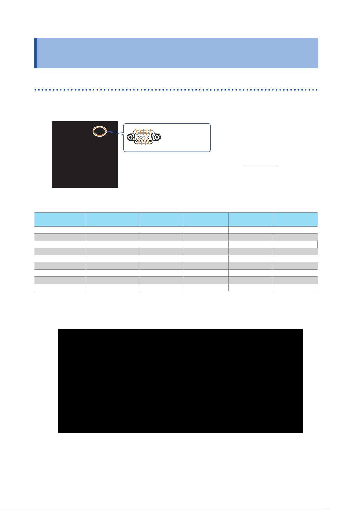
Connecting the RS-232C Cable
Connect the RS-232C cable to the RS-232C connector.
(Recommended cable: 9637 RS-232C cable)
Male 9-pin D-sub
#4-40 attaching
screws
To connect the instrument to a controller (DTE)
,
use a crossover cable compatible
with the connectors on both the instrument and the controller.
The I/O connector is a DTE (Data Terminal Equipment) conguration.
1 2 3 4 5
6 7 8 9
Connector (D-sub)
Pin No.
Interchange Circuit
Nam
e
CCITT
Circuit No.
EIA
Abbreviation
JIS
Abbreviation
Common
Abbreviation
1 Unused
2 Received Data 104 BB RD RxD
3 Transmitted Data 103 BA SD TxD
4
Data Terminal Ready
108/2 CD ER DTR
5 Signal Ground 102 AB SG GND
6 Unused
7 Unused
8 Unused
9 Unused
Example: Connecting to a DOS/V PC
Specication: D-sub 9-pin female and female connector
,
reverse connection