Manuelles Tray an D1 an Stellplatz 2 mit 2 Jedec - 第15页
Special Design 2 Assembly instructions Special design for manual tray at lo cation 2 for 2 Jede c trays SIPLACE D1 10/2007 Edition 15 2 Assembly instructions S pecial design for manual tray at location 2 for 2 Jedec tray…

1 Montageanleitung SOKO Manuelles Tray an Stellplatz 2 für 2 Jedec-Trays SIPLACE D1 SOKO
Ausgabe 10/2007
14
: Kleben Sie das SOKO Hinweis - Schild auf die rechte Abdeckung.
: Kontrollieren Sie die Kabelverlegung von den Endschaltern.
: Schalten Sie den Bestückautomaten am Hauptschalter ein und wechseln Sie in den SITEST.
: Stellen Sie die Endschalter ein und testen Sie die Funktion der Breitenverstellung sowie die
Funktion der Endschalter.
1.8 Hardware-Demontage
Die Demontage erfolgt in umgekehrter Reihenfolge. 1
1.9 Programmierung unter SIPLACE Pro
1
Verwenden Sie zur Programmierung unter SIPLACE Pro die Anleitung "Programmierhilfe Arbi-
trary Carrier unter SIPLACE Pro" (Art.Nr.: 00194607-xx). 1
1
1.10 Mögliche Fehlerursachen
Abholprobleme 1
– Die Trays sind nicht mit den beiliegenden Magneten fixiert worden.
Lösung: Trays nochmals fixieren.
– Die Trays sind nicht richtig in SIPLACE Pro beschrieben.
Lösung: Korrigieren Sie die Tray-Beschreibung.
– Bestückkopf holt an falscher Stelle ab.
Lösung: Offsetwerte laut Anleitung Arbitrary Carrier ermitteln und richtig eingeben.
– Die Trays haben keine bzw. falsche Offsetwerte.
Lösung: Ermitteln Sie die richtigen Offsetwerte (siehe Anleitung).
– Trayhalter wurde nicht richtig montiert.
Lösung: Ziehen Sie alle Schrauben fest an.
– Die Trays sind nicht spannungsfrei mit den beiliegenden Magneten fixiert.
Lösung: Trays nochmals fixieren.
1
Special Design 2 Assembly instructions Special design for manual tray at location 2 for 2 Jedec trays SIPLACE D1
10/2007 Edition
15
2 Assembly instructions
Special design for manual tray at
location 2 for 2 Jedec trays
SIPLACE D1
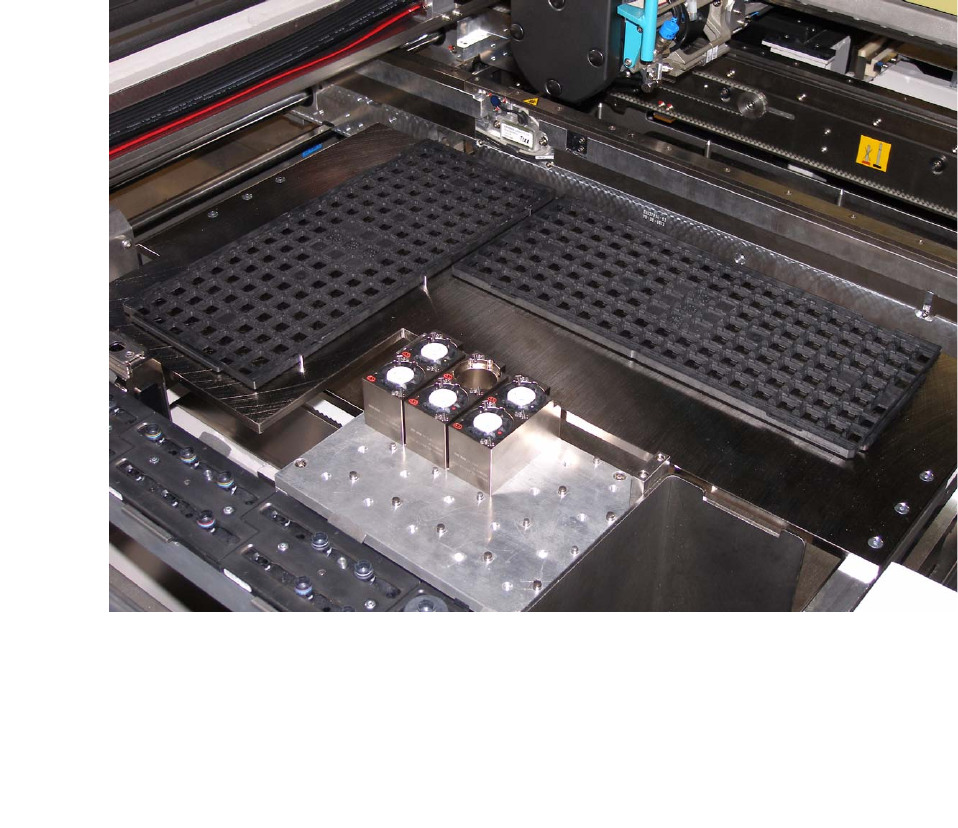
2.1 Working principle
At SIPLACE D1 it is possible to place a JEDEC Tray inside the machine. 2
2
2
2.2 Requirements
2
Hardware: SIPLACE D1 - single conveyor
Software: -

2 Assembly instructions Special design for manual tray at location 2 for 2 Jedec trays SIPLACE D1 Special Design
10/2007 Edition
16
2.3 Restrictions
The maximum conveyor width is approximately 300 mm with standard transport and 324 mm with
wide board transport. 2
The tray holder is intended solely for components which, including the tray, do not exceed 16 mm
in height. 2
If other components are to be placed in this tray holder, they must not be higher, otherwise there
is a risk of crashing with the placement head. 2
If a service tool is used, the machine must be set up with the standard setup once more. 2
Only a limited performance calculation is possible. 2
2
The restrictions concerning the component range still apply. 2
2
FlipChip camera and coplanarity module cannot be used. 2
Only fixed conveyor right can be used. 2
2.4 Scope of delivery
– Tray holder for location 2 (for 1 JEDEC Tray)
– 2 hexagon socket head screws M6 X 30 mm for tray holder
– Fixing bracket for limit switch
– 6 magnets for fixing the tray
– SOKO adhesive label
– Programming guide for arbitrary carrier under SIPLACE Pro (00194607-xx)
– Assembly instructions for tray holder SIPLACE D1 (00196049-xx).
2.5 Tools and consumables required
– Set of hexagon socket spanners
– Set of screw drivers
– Cable ties
– Self-adhesive cable clamps
–Side cutters
– Ethyl alocohol for cleaning
– Lint-free cloths.