Manuelles Tray an D1 an Stellplatz 2 mit 2 Jedec - 第19页
Special Design 2 Assembly instructions Special design for manual tray at lo cation 2 for 2 Jede c trays SIPLACE D1 10/2007 Edition 19 : Fit the tray holder to location 2 using th e two M6 x 30mm screws. Press the tray in…
2 Assembly instructions Special design for manual tray at location 2 for 2 Jedec trays SIPLACE D1 Special Design
10/2007 Edition
18
2.7 Hardware installation
2.7.1 Assembly of the tray holder
: Shut down the station computer and switch off the placement machine at the main switch.
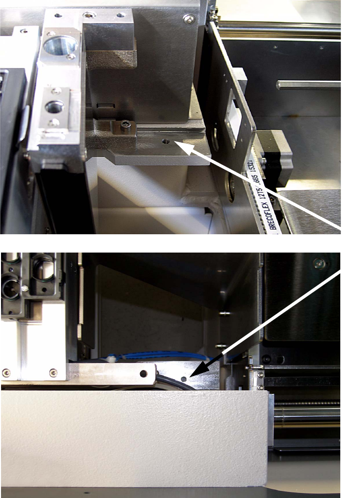
: Remove the component reject bin at location 2.
2
Thread for
tray holder
assembly
Special Design 2 Assembly instructions Special design for manual tray at location 2 for 2 Jedec trays SIPLACE D1
10/2007 Edition
19
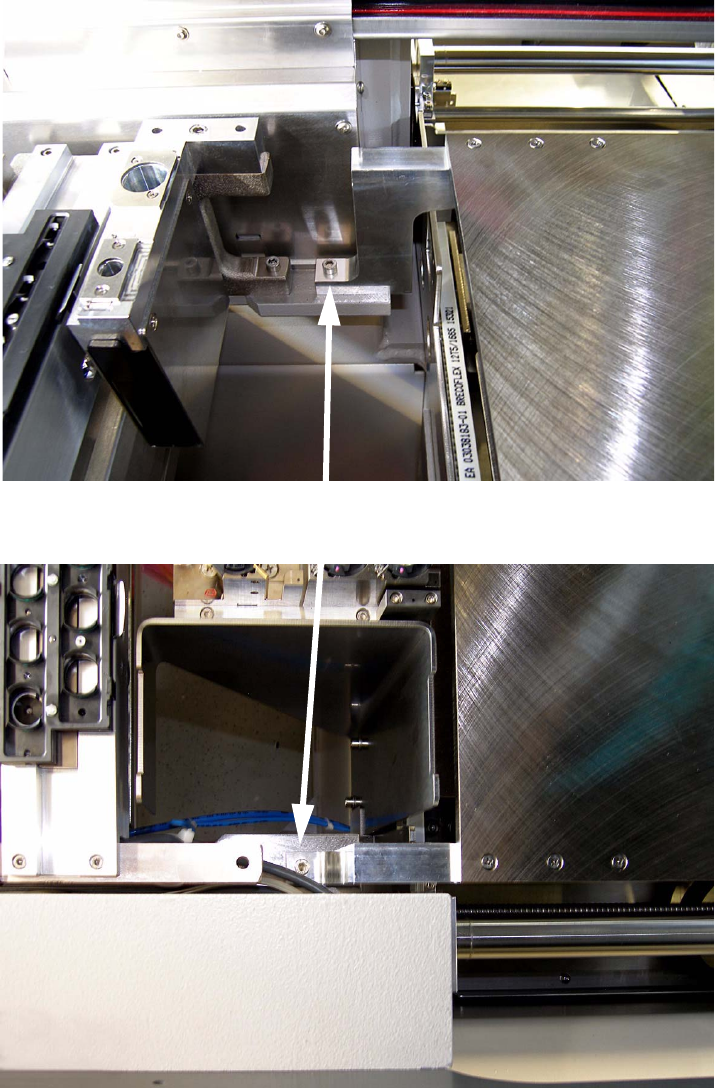
: Fit the tray holder to location 2 using the two M6 x 30mm screws.
Press the tray in direction to the component trolley.
2
: Insert the reject bin again.
Tray holder assembly with M6 x 30mm screws
2 Assembly instructions Special design for manual tray at location 2 for 2 Jedec trays SIPLACE D1 Special Design
10/2007 Edition
20
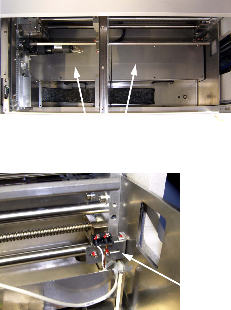
2.7.2 Adjusting the limit switch for the conveyor width
: Open the mini output flap.
: Remove the covers from the conversion board at the output conveyor.
2
2
: Disassemble the bracket for the right limit switch removing 2 screws.
2
Covers of conversion board
Bracket